 Loading...
Do you have a question about the Yamaha RX-V650 and is the answer not in the manual?
| Audio Decoding | Dolby Digital, DTS, Dolby Pro Logic II |
|---|---|
| Tuner | AM/FM |
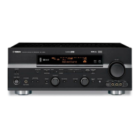
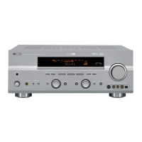
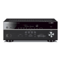
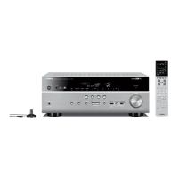
| Type | AV Receiver |
| Channels | 7.1 |
| Component Video Inputs | 3 |
| Component Video Outputs | 1 |
| Digital Audio Outputs | 1 Optical |
| Total Harmonic Distortion | 0.06% |
| Input Sensitivity/Impedance | 200 mV/47 k ohms |
| Signal-to-Noise Ratio | 100 dB |
| Inputs | Analog Audio: 6 |
| Video Inputs | Component: 3 |
| HDMI Inputs | No |
| Digital Audio Inputs | 2 Optical, 2 Coaxial |
| Frequency Response | 10Hz-100kHz (+0/-3dB) |
| Amplifier Output | 95 W/ch (8 ohms, 20 Hz-20 kHz, 0.06% THD) |
| Video Inputs/Outputs | Composite: 5 in / 2 out |