–13–
EBA00024
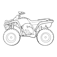
6. CLUTCH AND PARKING
BRAKE LEVER
ASSEMBLY
A: Install the clutch and parking
brake lever assembly as
shown.
(a) 53 ~ 54 mm (2.09 ~ 2.13 in)
B: Tighten the bolts to specifica-
tion.
C: Check the clutch lever for
smooth operation.
WARNING
_
Proper cable routing is essen-
tial to assure safe machine
operation. Refer to “CABLE
ROUTING”.
T
R
.
.
Bolt
4 Nm
(0.4 m · kg, 2.9 ft · lb)
EBA00025
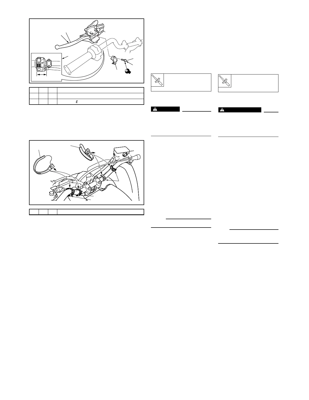
7. CABLE TIES
(HANDLEBAR)
A: Fasten the handlebar switch
lead and the clutch switch lead
to the handlebar with a plastic
band.
B: Fasten the starter cable, han-
dlebar switch lead, and clutch
switch lead to the handlebar
with a plastic band.
C: Fasten the front brake light
switch lead to the handlebar
with two bands.
NOTE:
_
Refer to “CABLE ROUTING”.
1(3)- 1
2 (3)-V 1
3 (3)-V 2 d = 5 (0.20), = 16 (0.63)
2
3
B
1
C
4
A
a
1 (4)-V 4
1
A
B
1
C
FBA00024
6. COMBINÉ LEVIER
D’EMBRAYAGE ET
FREIN DE
STATIONNEMENT
A: Monter le combiné levier
d’embrayage et frein de station-
nement comme illustré.
(a) 53 à 54 mm (2,09 à 2,13 in)
B: Serrer les vis au couple spécifié.
C: Contrôler le bon fonctionnement
du levier d’embrayage.
AVERTISSEMENT
_
Le cheminement correct des câbles
est indispensable à la sécurité du
véhicule. Se reporter à “CHEMI-
NEMENT DES CÂBLES”.
T
R
.
.
Vis
4 Nm
(0,4 m · kg, 2,9 ft · lb)
FBA00025
7. ATTACHES DE CÂBLES
(GUIDON)
A: Attacher le fil du combiné de
contacteurs et le fil du contacteur
d’embrayage au guidon à l’aide
d’un collier réutilisable.
B: Attacher le fil du démarreur, le fil
du combiné de contacteurs et le
fil du contacteur d’embrayage au
guidon à l’aide d’un collier réuti-
lisable.
C: Attacher le fil du contacteur de
feu stop sur frein avant au guidon
à l’aide de deux colliers réutilisa-
bles.
N.B.:
_
Se reporter à “CHEMINEMENT
DES CÂBLES”.
 Loading...