4-13
IM 01F06A00-01E
4. BASIC OPERATING PROCEDURES
4.6 Operation via HART configu-
ration tool
NOTE
This chapter describes the digitalYEWFLO as an
example.
Note: HART is a registered trademark of the HART Communication
Foundation.
4.6.1 Matching of instrument
(digitalYEWFLO) DD and HART
Configuration Tool’s DD
Before using the HART Configuration Tool (such as
FieldMate), confirm that the DD (Device Description) of the
digitalYEWFLO is installed in the Configuration Tool before
using.
The DD revisions for digitalYEWFLO and Configuration
Tool’s can confirm in accordance with the following steps.
If the correct DD is not installed in the HART Configuration
Tool, download them from the official HART programming
sites, otherwise, contact the respective vendors of the
Configuration Tool for its upgrade information.
1. Confirmation of the device revision for
digitalYEWFLO
(1) Connect the Configuration Tool to the
digitalYEWFLO.
(2) Select the “5.Device information” menu.
(3) Open the “7.Revision numbers” menu.
(4) The device revision of the digitalYEWFLO is
displayed at “2.Fld dev rev.”
2. Confirmation of the device revision for the HART
Configuration Tool
(1) Turn on the power of the Configuration Tool
under the standalone condition.
(2) Confirm the installed DD revision in accordance
with the procedure of the Configuration Tool.
Refer to its manual how to confirm it in detail.
The first 2 digits of the DD file are expressed
the device revision, and its last 2 digits are
expressed the DD revision.
01 01.XXX
DD revision
Device revision
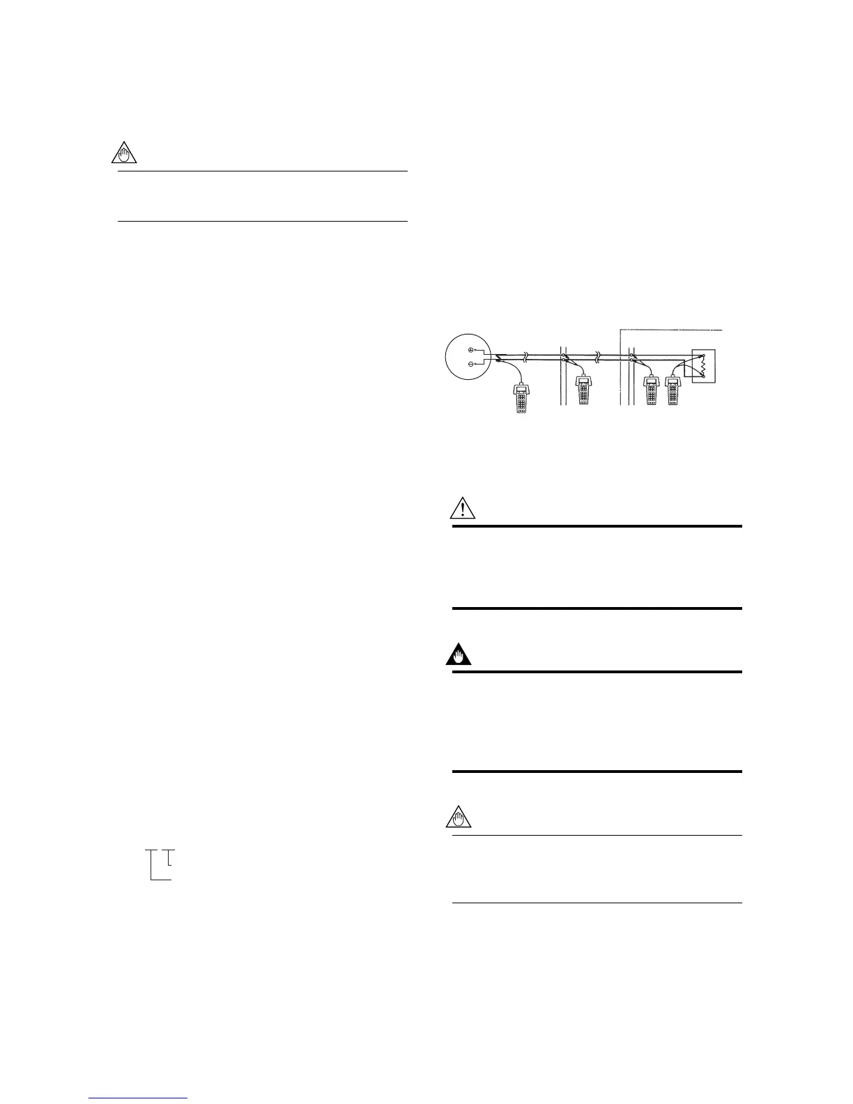
4.6.2 Interconnection between
digitalYEWFLO and HART Configu-
ration Tool
The HART Configuration Tool can interface with the
digitalYEWFLO from the control room, the digitalYEWFLO
site, or any other wiring termination point in the loop,
provided there is a minimum load resistance of 250 Ω
between the connection and the receiving instrument. To
communicate, it must be connected in parallel with the
digitalYEWFLO, and the connections must be non-polarized.
Figure 4.6 illustrates the wiring connections for a direct
interface at the digitalYEWFLO site. The HART Configura-
tion Tool can be used for remote access from any terminal
strip as well.
+
–
4 to 20 mA DC signal line
Control room
Te r minal board
Receiving instrument
load resistance:
250 Ω to 600 Ω
Relaying
terminals
HART
Configuration Tool
HART
Configuration Tool
HART
Configuration Tool
F040602.EPS
digitalYEWFLO
SUPPLY
SUPPLY
Figure 4.6 Connecting the HART Communicator
WARNING
Be sure to set parameters as “Protect” on the write
protect function after finish of parameter setting work.
Refer to 4.6.7 Write Protect how to use the write
protect function in detail.
IMPORTANT
If the power of flowmeter is turned off within 30
seconds after parameters have been set, these
settings will be canceled. Accordingly, please keep the
power on for at least 30 seconds after setting param-
eters.
 Loading...


