4.InstallationSpecications
4-2
TI 32P01J10-01EN
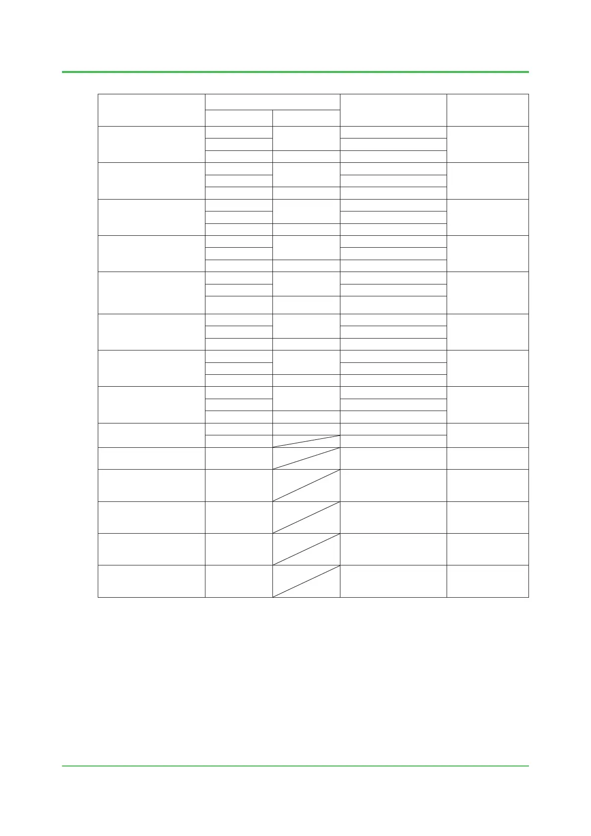
Equipment
Input voltage range
Maximum power
consumption/current
dissipation (*1), VA, A
Heating value, J/h
(*2)
Voltage, V AC Frequency, Hz
S2SC70S-S Safety
Control Unit
100-120
50 or 60 ± 3
200 VA
432 x 10
3
(120 W)220-240 230 VA
24 V DC 5.5 A
S2SC70S-F Safety
Control Unit
100-120
50 or 60 ± 3
240 VA
540 x 10
3
(150 W)220-240 290 VA
24 V DC 7.0 A
S2SC70D-S
Duplex Safety Control
Unit
100-120
50 or 60 ± 3
200 VA
432 x 10
3
(120 W)220-240 230 VA
24 V DC 5.5 A
S2SC70D-F
Duplex Safety Control
Unit
100-120
50 or 60 ± 3
240 VA
540 x 10
3
(150 W)220-240 290 VA
24 V DC 7.0 A
SNB10D Safety
Node Unit
(with maximum number of
I/O Modules Installed)
100-120
50 or 60 ± 3
200 VA
432 x 10
3
(120 W)
220-240 230 VA
24 V DC 5.5 A
SNT10D Unit for Optical
Bus Repeater Module
100-120
50 or 60 ± 3
200 VA
432 x 10
3
(120 W)220-240 230 VA
24 V DC 5.5 A
AVR10D
Duplexed V net router
100-120
50 or 60 ± 3
80 VA
158 x 10
3
(44 W)220-240 110 VA
24 V DC 1.7 A
AW810D
Wide Area
Communication Router
100-120
50 or 60 ± 3
80 VA
158 x 10
3
(44 W)220-240 110 VA
24 V DC 1.7 A
S2NN30D
Node Interface Unit
100-240 50 or 60 ± 3 190 VA
90 x 10
3
(25 W)
24 V DC 150 W
S2BN1D
Base Plate
24 V DC 24 W 51 x 10
3
(14 W)
S2BN4D
Base Plate for Barrier
(MTL) System Power
24 V DC 24 W 51 x 10
3
(14 W)
S2BN4D
Base Plate for Barrier
(MTL) Barrier Power
24 V DC 38.4 W 83 x 10
3
(23 W)
S2BN5D
Base Plate for Barrier
(P+F) System Power
24 V DC 24 W 51 x 10
3
(14 W)
S2BN5D
Base Plate for Barrier
(P+F) Barrier Power
24 V DC 28.8 W 58 x 10
3
(16 W)
*1: The power consumption in steady operation is indicated in VA (AC) or A (DC). When the power consumption varies according to
the installed number of equipment, the power consumption by the maximum number of units installed is listed.
*2: The heating value in steady operation is indicated in Joule/hour. When the heating value varies according to the installed number
of equipment, the heating value by the maximum number of units installed is listed.
Nov. 27, 2015-00
Table Electrical Specications (2/2)