1. System Installation Requirements
1-16
TI 32P01J10-01EN
In-Rush Current
When the equipment is turned on, a large in-rush current ows as the capacitor is
instantaneously charged and the transformer is excited. When any equipment is turned on, this
should not cause any voltage uctuation that could adversely aect other equipment. Do not turn
on all equipment at the same time. Start equipment one by one.
Power may be switched to backup or AC line power if in-rush current activates the overload
protection circuit on power-up. After such an overload, select an uninterruptible power unit, with
automatic-recovery.
Suppressing Harmonic Current
In order to suppress harmonic current supplied to a low-voltage distribution system, it is
necessary to install a power unit or an active harmonic suppressor, such as indicated below,
between a device and the distribution system:
• Power unit equipped with the harmonic suppression function (a high power-factor inverter-
type uninterruptible power unit, etc.)
• Active harmonic suppressor
In Europe, a power unit should be selected so that harmonic current emissions are within the
limits specied by EMC regulations.
The capacity of the harmonic suppression unit should be determined in consultation with a power
unit manufacturer in the same manner as the selection of power unit’s output capacity previously
discussed.
Notes for the eld power supply unit of N-IO
As described in GS 32P06K20-01EN “Base Plate (for N-IO)”, field power supply (24 V DC)
is required when Digital output function of the base plate with disconnecting terminal (Model
S2BN1D) is utilized.
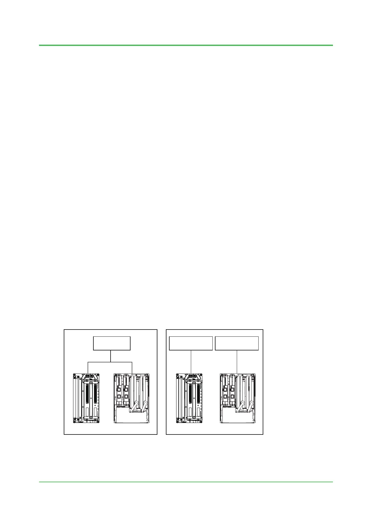
When using the node interface unit S2NN30D-4 (24 V DC power input type)
in combination with S2BN1D and the power supply unit as shown on the left side of the figure
below, it is recommended to separate the power supply as shown in right.
This is because the rapid change of the field output load of S2BN1D may causes an influence on
24 V power line, it is worried that the input voltage rating of S2NN30D will not be satisfied.
F010305.ai
TM1
TM2
BUS1 BUS2
SYS
PWR
FLD
PWR 24V
NODE
UNIT
Power supply
24 V DC
S2BN1D S2NN30D S2NN30D
TM1
TM2
BUS1 BUS2
SYS
PWR
FLD
PWR 24V
NODE
UNIT
Field power supply
for S2BN1D
24 V DC
Power supply
for S2NN30D
24 V DC
S2BN1D
RecommendedUnrecommended
Figure Connection of the eld power supply of S2BN1D
Mar. 15, 2018-00
 Loading...