2. Transportation, Storage and Installation
2-16
TI 32P01J10-01EN
Installation of DIN Rail
• Install a DIN rail in a metal mounting plate with screws at 120-mm or less intervals.
• When mounting a DIN rail mountable device to a DIN rail, conrm that the device is securely
xed after the mounting.
• A DIN rail for S2BN1D must be electrically insulated from a cabinet using insulating bushing.
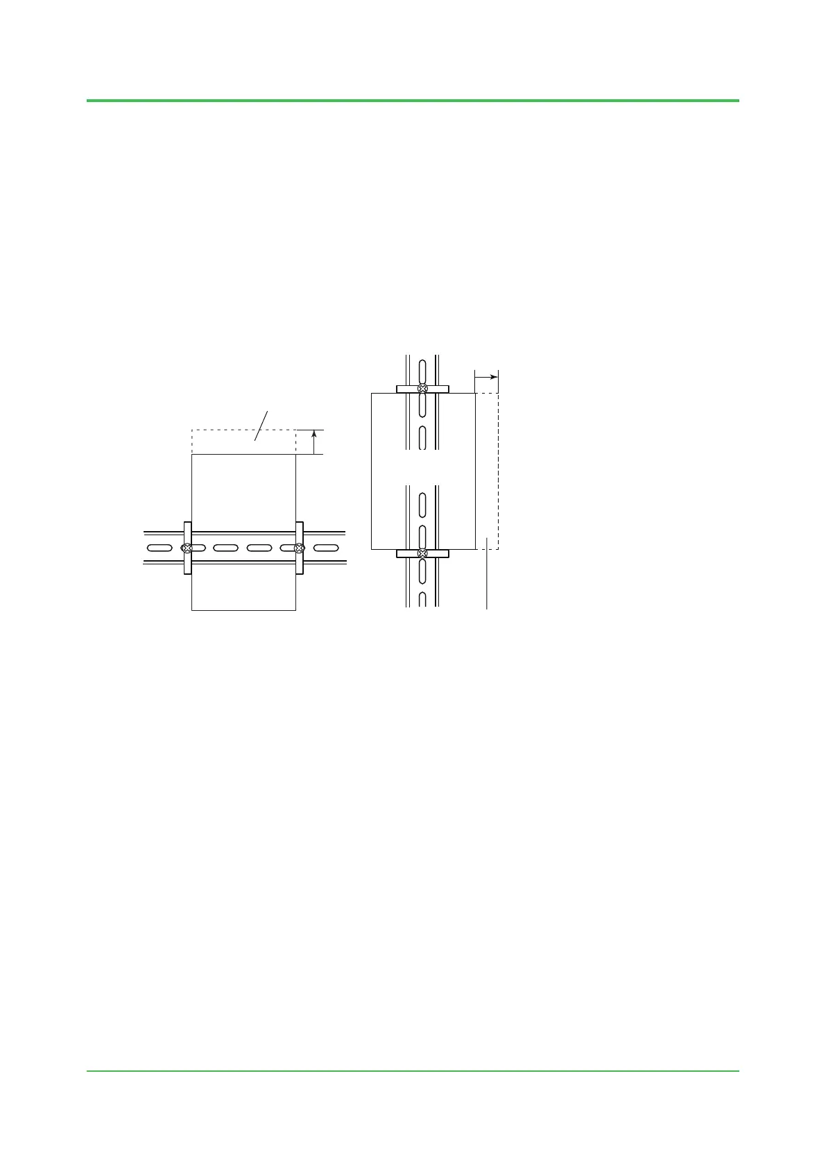
Mounting Space
S2NN30D and S2BN1D require spaces, as shown below, to slide in to the positions when
mounting to the DIN rail. Refer to the General Specications (GS) for the external dimensions.
F020525.ai
+10 mm
A space for mounting
on the right side of the unit is required.
I/O unit
mounting position
+10 mm
A space for mounting
above the unit is required.
Node Interface Unit:
S2NN30D-0
I/O unit: S2BN1D-0
Node interface unit
mounting position
Figure Mounting Space (Front View)
Grounding
Be sure to ground the equipment using the ground terminal of the base plate. Even if there is
electrical conduction between the base plate and wall surface via the mounting mechanism, the
equipment must be grounded using the functional ground terminal.
Oct. 25, 2016-00
 Loading...