<4. START OF OPERATION>
4-1
IM 01R01B02-00E-E 12th edition October 01, 2014 -00
All Rights Reserved. Copyright © 2003, Rota Yokogawa
4. Start of operation
4.1 Hints on ow rate measurement
The measured uid should neither consist of a multi-phase mixture nor contain ferrite ingredients or large solid
mass particles.
The RAMC scale is adjusted to the state of operation/aggregation of the measured uid by the manufacturer. If
the state of operation changes, it might become necessary to establish a new scale. This depends on several
factors:
- If the RAMC is operated in the given viscosity independent range, only the density of the oat as well as the
operational density of the previous and new substance have to be considered. In case the operational
density only changes marginally (≤ 0.5%), the present scale can be used.
- If the RAMC is operated outside the given viscosity independent range, the viscosities at the previous and new
state of operation as well as the mass and diameter of the oat have to be taken into account.
4.2 Pulsation and pressure shock
Pressure shock waves and pulsating ow inuence measurement considerable or can destroy the meter. Surge
conditions should be avoided. (open valves slowly, raise operating pressure slowly)
If oat bouncing occurs in gases increase the line pressure until the phenomena stop. If this is not possible
provide the oat with a damper. A damping kit is available as spare part.
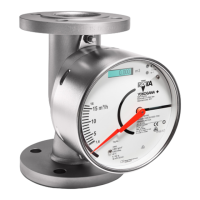
4.3 Start of operation of electronic transmitter
Ensure that the device has been connected correctly according to section 3-2 and that the used power supply
meets the requirements indicated on the scale.
Switch on the power supply.
The digital display gives the totalizer value in the measuring unit, indicated on the right side of the display.
The RAMC is now ready for operation.
Unit graduation, measuring unit, damping, etc. can be adjusted by an operating menu (refer to section 6.2). In
case of an error, the bars beneath the 8 digits of the display will ash. The corresponding error message can
be checked using the operating menu and then taking the appropriate counter measures (refer to section
6-2-8 “Error Messages”).
The transmitter has been prepared and calibrated according to the model code as a 2-, 3- or 4-wire unit.
In 2-wire units, a jumper connects “A” and “-”. When switching from a 2- to a 3-wire conguration, this jumper
should be removed. The current output should then be adjusted as explained in section 6-2-6.
When changing from a 3- to 2-wire conguration, the jumper should be set in place, and the current output
has to be adjusted according to section 6-2-6.

 Loading...