<9. TECHNICAL DATA>
9-18
IM 01R01B02-00E-E 12th edition October 01, 2014 -00
All Rights Reserved. Copyright © 2003, Rota Yokogawa
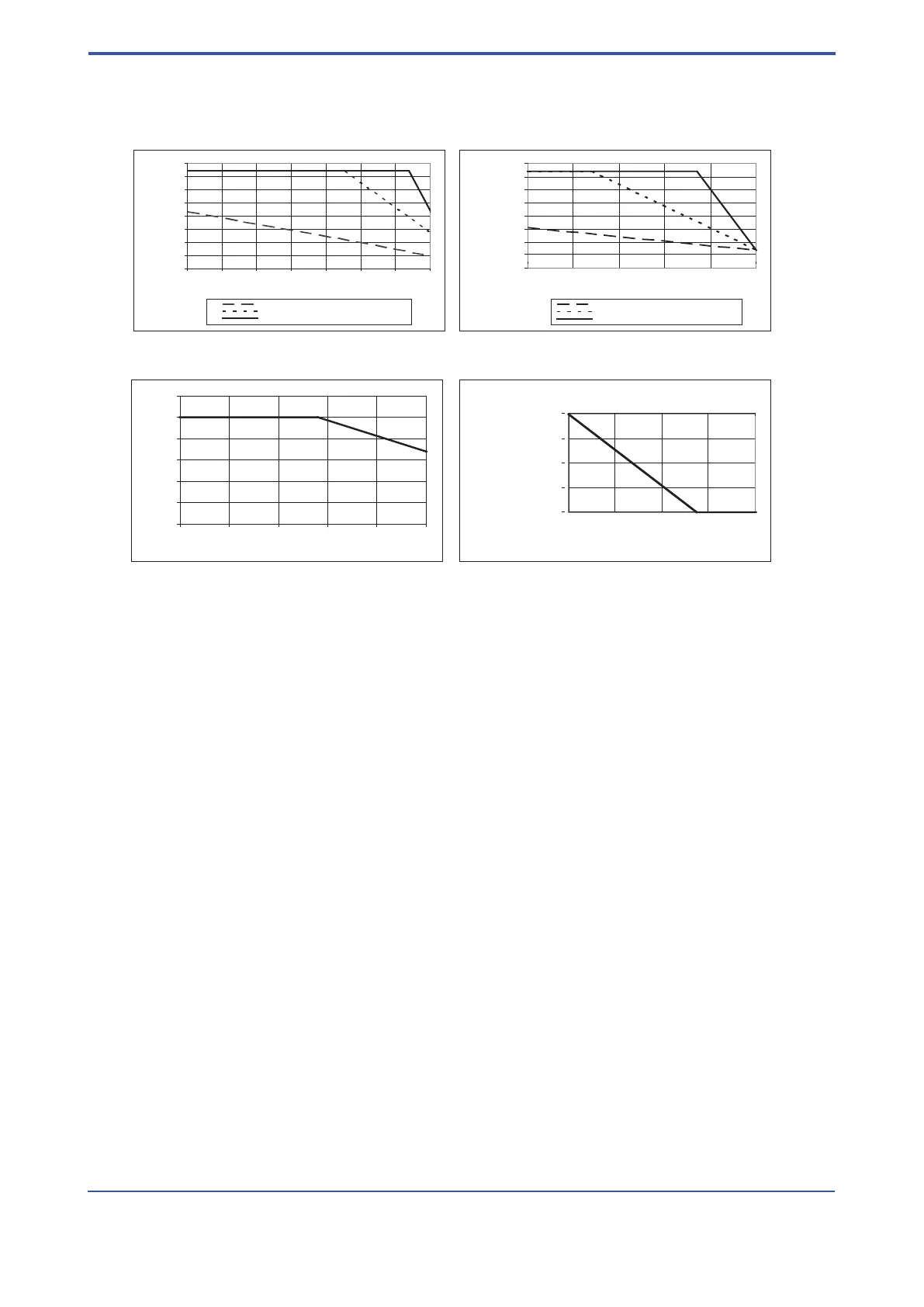
9.5 Temperature graphs for RAMC metal design,
standard and intrinsic safe
0
50
100
150
200
250
300
350
400
20 30 40 50 60 70 80 90
max process temperature [°C]
without option /A16
with option /A16 and insulation
with option /A16, no insulation
0
50
100
150
200
250
300
350
400
20 30 40 50 60 70
Ambient temperature [°C]
max process temperature [°C]
without option /A16
with option /A16 and insulation
with option /A16, no insulation
-200
-150
-100
-50
0
-30 -20 -10 0
min process temperature [°C]
Low temperature curve
with option /A16 and insulation
0
20
40
60
80
100
120
20 30 40 50 60 70
max. process temperature [°C]
fig. 7a RAMC : - type 90 / 91
- only with indicator
fig. 7b RAMC : - type 90 / 91
- with limit switches
- with electronic transmitter
fig. 7d RAMC : - type 90 / 91
- with or without limit switches
- with or without electronic transmitter
fig. 7c RAMC : - type 66
- with or without limit switches
- with or without electronic transmitter
-40
The temperature graphs are reference values for size DN100. They may be inuenced negative by trapped heat, external heat
sources or radiated heat and inuenced positive for smaller sizes.
Insulation means rock wool between tube and indicator.
Units with electronic transmitter can show the temperature of the internal transmitter on the display or HART- type can show
and supervise the internal temperature by HART-communication.
Units with PTFE lining are usable up to 130°C.
For units with explosion proof certication the temperature limits according the certicate of conformity must be regarded (see
also page 9-8 to 9-11).

 Loading...