<6. ELECTRONIC TRANSMITTER (-E)>
6-1
IM 01R01B02-00E-E 12th edition October 01, 2014 -00
All Rights Reserved. Copyright © 2003, Rota Yokogawa
6. Electronic Transmitter (-E)
6.1 Operation principle
The position of the oat is magnetically transferred to a magnetic follow up system. The position angle of this
magnetic rocker is detected by magnet sensors. A micro controller determines the angle by means of a
combining reference value table in the memory and calculates the ow rate by the angle with calibration and
operation parameters the calibration EEPROM. The ow rate is given as a current, either 0-20 mA or 4-20 mA,
and, in addition, indicated on the digital display (refer also to section 6-2). The electronic transmitters have been
electronically adjusted before shipping and, therefore, are mutually exchangeable.
Calibration data of the metering tube as well as customer specic data are entered into a calibration EEPROM,
inserted on the board. This calibration EEPROM and the indication scale are assigned to the respective
metering tube.
When replacing an indicator (e.g. because of a defect) the scale and calibration EEPROM of the old unit have
to be inserted in the new unit. Then, no calibrations or adjustments are necessary.
If an indicator with electronic transmitters is installed to a new metering tube, the calibration EEPROM of that
tube has to be inserted into the transmitter and the indicator scale for that particular tube has to be mounted.
A change in the uid data (e.g. specic gravity, pressure, etc.) requires the preparation and mounting of
a new calibration EEPROM and scale.
Normally the range of the current output is equal to the rounded measuring range of the tube (end value on
scale). The customer can position the 20 mA point between 60% and 100% of the end value on scale. The set
of the 20 mA point is shown on the scale (refer to Fig. 1-4). The ow cut off is positioned at 5% of the end value.
Below 5% ow the current output shows 0 mA (4 mA).
6.2 Parameter setting
The displays allows indication of various parameters:
• Flow rate (8 mass or volume units in combination with 4 time units)
• Counter (8 mass or volume units)
• Flow rate indication in percent
• Special functions:
• Setting of different damping times
• Switching of current output 0-20 mA / 4-20 mA or vice versa
• Indication of error messages
• Manual adjustment
• Service functions
• Detection of oat blockage
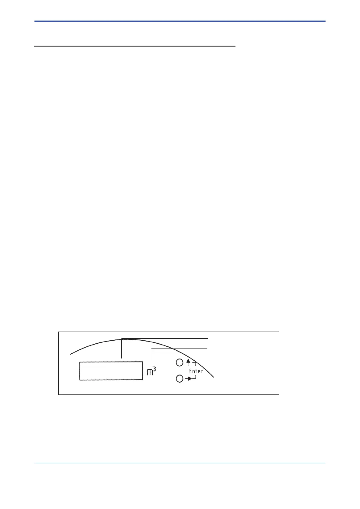
The setting of these parameters is done by two buttons.
Fig. 6-1 Operation keys
F61.EPS
Digital display
Engineering unit of the display
Operation keys

 Loading...