Measuring principle and flow meter design
General Instruction Manual
Product specification
IM 01U10B00-00EN-R, 3rd edition, 2018-07-09
11 / 90
4.2 Measuring principle and flow meter design
4.2.1 Measuring principle
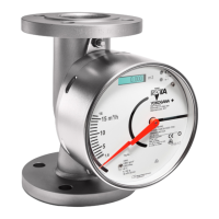
The measuring principle is based on the generation of Coriolis forces. For this purpose, a
driver system (E) excites the two measuring tubes (M1, M2) in their first resonance fre-
quency. Both pipes vibrate inversely phased, similar to a resonating tuning fork.
A
E
F1
S1
S2
F2
M1
Q
M2
-F1
-F2
-A
inlet
outlet
Fig.1: Coriolis principle
M1,M2 Measuring tubes E Driver system
S1, S2 Pick-offs A Direction of measuring tube
vibration
F1, F2 Coriolis forces Q Direction of fluid flow
Mass flow
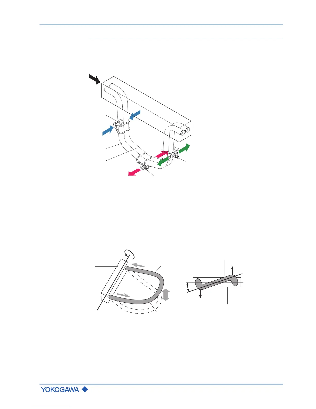
The fluid flow through the vibrating measuring tubes generates Coriolis forces (F1, -F1
and F2, -F2) that produce positive or negative values for the tubes on the inflow or out-
flow side. These forces are directly proportional to the mass flow and result in deforma-
tion (torsion) of the measuring tubes.
Fig.2: Coriolis forces and measuring tube deformation
1 Measuring tube mount A
E
Rotational axis
2 Fluid F1, F2 Coriolis forces
3 Measuring tube α Torsion angle
 Loading...