36
JOHNSON CONTROLS
FORM 100.50-NOM6 (1207)
Installation
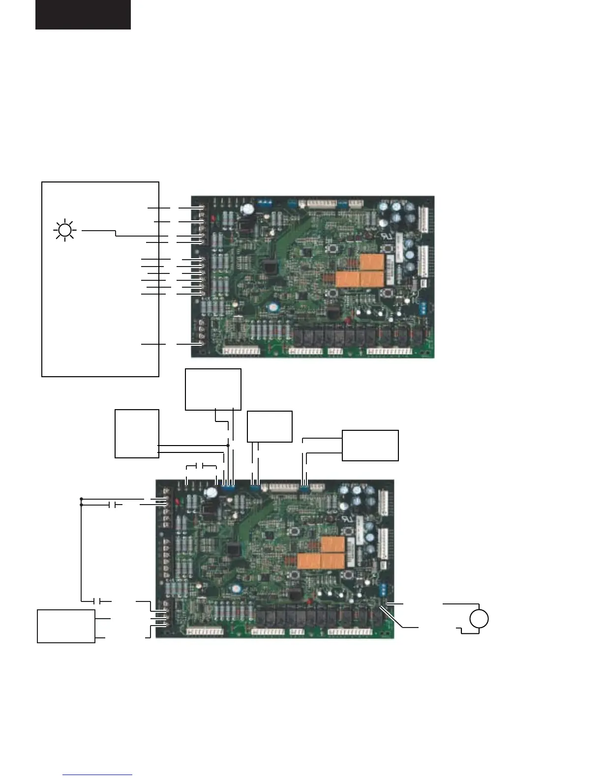
FIG. 2-8 – FIELD CONTROL WIRING CONNECTIONS
LD13002
Wiring Notes:
1. Wiring shown indicates typical wiring. Refer to the IOM manual for more detailed wiring methods and options.
2. All wiring is Class 2, low voltage.
3. Maximum power available from the 24 VAVC terminal is 40 VA.
4. Use shielded wire where shown.
FIELD CONTROL WIRING CONNECTIONS
Y4 (Cool Stage 4)
Y4
Y3 (Cool Stage 3)
Y3
Y2 (Cool Stage 2)
Y2
Y1 (Cool Stage 1)
Y1
W3 (Heating Stage 3)
W3
W2 (Heating Stage 2)
W2
W1 (Heating Stage 1)
W1
G (Fan)
G
R(24VAC)
R
C (Common)
C
X
FAULT
LIGHT
(Optional)
10 WIRE THERMOSTAT
R
OCC
PURGE
BAS ECON +
BAS ECON -
Use shielded wire
BAS ECONOMIZER
INPUT
0-10 VDC
(Field Supplied)
VAV OPEN +
VAV OPEN -
VAV HEAT RELAY
24 VDC
RELAY
(Field Supplied)
CO2 SENSOR
(Field Supplied)
0-2000 PPM
0-10 VDC OUTPUT
Use Shielded
Wire
Use Shielded Wire
Use
Shielded
Wire
DV+
DV-
SUPPLY AIR
TEMP RESET
0-10 VDC
(Field Supplied)
REM +
ST
SD1
R
REM -
GND
SSO
SPACE
SENSOR
10K TYPE III
THERMISTOR
COM
TMP
SPACE SENSOR
RESET
20K ADJUST
POTENTIOMETER
COM SET
Shutdown
 Loading...