EZ Zone/Meridian
16 Upgrade
036-21423-001 Rev. A (0602)
EZ Zone Wiring
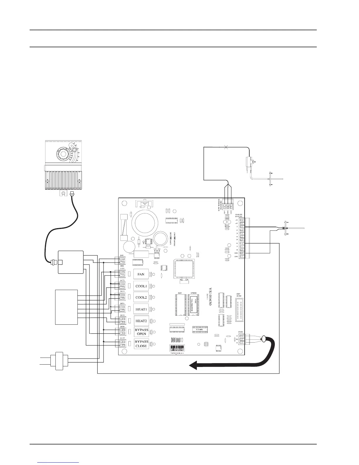
The wiring diagram below depicts a typical existing
EZ Zone Master Controller wiring. This diagram is
shown for reference only. It’s intent is to show the dif-
ference between the EZ Zone system wiring and the
Meridian system wiring. All wiring should be connected
per the specific Meridian system wiring diagrams on
the following pages.
Static
Pick-up
Static
Pressure
Sensor
Supply Air
Temp Sensor
Splice As
Required
LO HI
HVAC Unit
24VAC Only
R
G
Y1
Y2
W1
W2
Line
Voltage
GND
24VAC
Actuator Wiring
Interface
Feedback (BK)
Close (GR)
Open (YL)
Gnd (WH)
Bypass Air Damper
Actuator
Red
Blk
Grn
RS-485
Communication cable
to Zone Controllers
Master Controller Board
75
90
60
45
Figure 1: Existing EZ Zone Master Controller Wiring

 Loading...
