EZ Zone/Meridian
20 Upgrade
036-21423-001 Rev. A (0602)
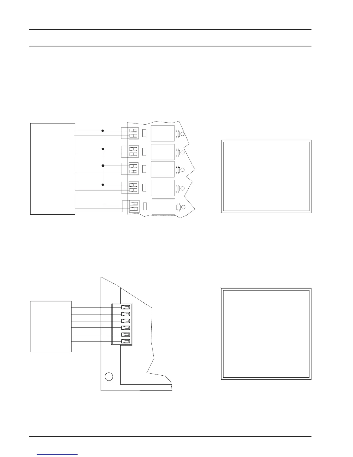
HVAC Staging Connections
Figure 6: New Meridian HVAC Wiring
Figure5 below shows the EZ Zone Master Controller
wiring. Figure 6 below depicts the wiring schematic
that should be used for wiring of all Meridian Zone
Managers boards. As can be seen below, the Meridian
OUT1
OUT2
OUT3
OUT4
OUT5
FAN
COOL1
COOL2
HEAT1
HEAT2
24VAC-R
Fan-G
Cool - Y1
Cool - Y2
Heat - W1
Heat - W2
HEAT2
HEAT1
COOL2
COOL1
FAN
R
Fan-G
Cool - Y1
Cool - Y2
Heat - W1
Heat - W2
24 VAC -R
Figure 5: Existing EZ Zone HVAC Wiring
The EZ Zone Master Con-
troller relay outputs consist
of a series of five double pole
terminal blocks. Wire jump-
ers between terminal blocks
are required to the common
of each relay.
The Meridian Zone Manager
wiring has been simplified.
There is only one terminal
block with connections
clearly marked for ease of in-
stallation. Jumpers are no
longer required since the
commons are tied together
within the circuit board.
Zone Manager wiring is much simpler than the EZ Zone
Master Controller wiring. Be sure to pay strict atten-
tion to all warnings and cautions listed on the sche-
matic.

 Loading...
