EZ Zone/Meridian
30 Upgrade
036-21423-001 Rev. A (0602)
Minilink Board
Zone Manager Board
Keypad And Display
Circuit Board
3- Connector Ribbon Cable
To KeyPad & Display Board
See Connection Detail Below
Cable Connection Detail
+
+
+
+
+
+
+
+
+
HEAT2
HEAT1
COOL2
COOL1
FAN
R
2
8
C
SW1
16
A
B
2
4
ADD
LOCAL
LOOP
T
SH
R
TB3
COMM
T
SH
R
32
16
8
4
1
2
MINILINK
R9
R10
R8
IC
EXP
PORT
PWR
V4
V3
CLOSE
OPEN
FDBK
REC
GND
GND
24VAC
AUX1
OPEN
K1
NETWORK
LOOP
SH
R
T
CLOSE
K2
NE5090
ANALOG
OUTPUTS
A2
G
TB2
A1
N.O.
EXHAUST
CONTACTS
GND
GND
AUX3
AUX2
7824
D25
U14
VR3
R40
ADJUST
5.11V
C27
7812
C26
VR2
D1
D3
D4
D2
PJ1
PRESSURE
SENSOR JACK
+5V
R7
OAT
RAT
+12V
SAT
ANALOG
INPUTS
GND
SIG
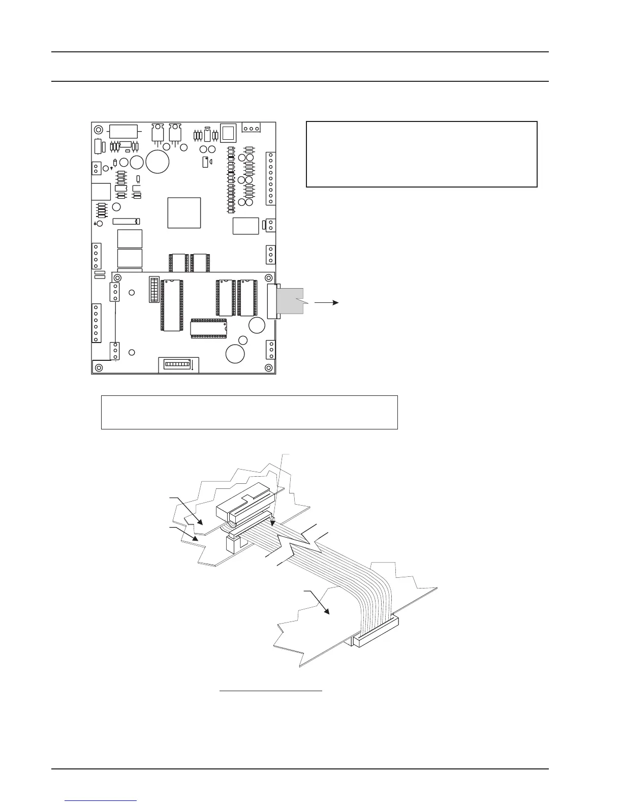
Use 3-Connector Ribbon Cable When Connecting
Auto-Zone Plus Zone Manager Board
To EZ Zone Keypad & Display Board
USE CARE TO ROUTE THE RIBBON CABLE SO THAT IT IS NOT CRIMPED AND SO
IT IS CLEAR OF ENCLOSURE COVER SCREWS WHEN INSTALLED
CAUTION!
Figure 18: 3 Connector Ribbon Cable Installation
Note:
The 3 Connector Ribbon Cable Is Only Required
When Connecting A System As Shown In
Example #2 On Pages 10 & 11 Of This Guide.
Ribbon Cable Installation

 Loading...
