EZ Zone/Meridian
Upgrade 21
036-21423-001 Rev. A (0602)
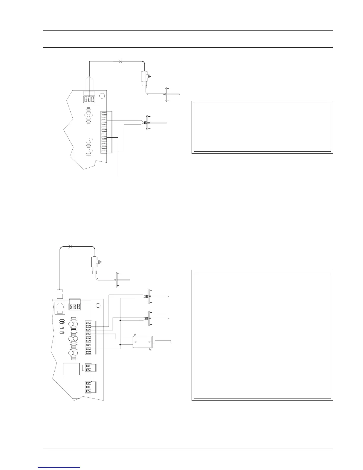
Sensor Connections
Figure 8: New Meridian Zone Manager Sensor Wiring
ANALOG
INPUTS
+V
+V
1
2
3
4
5
6
7
8
G
G
PRESSURE
SENSOR
+5V
SIG
GND
TB12
Static
Pick-up
Static
Pressure
Sensor
Splice As
Required
LO HI
Red
Blk
Grn
Supply Air
Sensor
To Bypass
Actuator Feedback
+
+
+
+
R9
R10
C4
R8
AUX1
ANALOG
OUTPUTS
A2
G
TB5
TB4
TB3
A1
N.O.
CONTACTS
EXHAUST
GND
GND
AUX3
AUX2
D3
D4
D5
D6
D8
D2
PRESSURE
SENSOR JACK
+5V
R7
INPUTS
OAT
RAT
+12V
SAT
ANALOG
GND
SIG
TB1
PJ1
Return Air Temp.
Sensor
Supply Air Temp.
Sensor
Outdoor Air Temp.
Sensor
Static
Pick-up
Static
Pressure
Sensor
Splice As
Required
LO HI
Figure 7: Existing EZ Zone Master Controller Sensor Wiring
The EZ Zone Master Controller sensor connec-
tions are located on the right side of the board.
Only a supply air temperature sensor and the
bypass actuator feedback are connected here.
The Meridian Zone Manager includes terminals
for connecting the following sensors:
• Supply Air Temperature
• Return Air Temperature
• Outside Air Temperature
The terminals are marked SAT, RAT, and OAT
for ease of wiring. Auxiliary input terminals
AUX1, AUX2 and AUX3 are used for Econo-
mizer Disable, Dirty Filter Alarm and Forced
Occupied Mode. Bypass damper feedback has
been relocated (see next page).

 Loading...
