404912-UIM-A-0508
Johnson Controls Unitary Products 3
The coil is provided with a secondary drain. It should be piped to a loca-
tion that will give the occupant a visual warning that the primary drain is
clogged. If the secondary drain is not used it must be capped.
6. When an evaporator coil is installed in an attic or above a finished
ceiling, an auxiliary drain pan should be provided under the coil as
is specified by most local building codes.
7. Proper electrical supply must be available.
HORIZONTAL DRAIN PAN CONVERSION
These air handler units are supplied ready to be installed in a right hand
horizontal position. If unit requires left hand positioning, the unit must
have the pan installed in the correct position. Conversion must be made
before brazing the refrigerant connections to the coil.
1. Remove blower access, coil access, and center access panels.
2. Remove two screws from horizontal drain pan, to remove pan from
position “3A” if factory installed. See Figure 3.
3. Position horizontal pan, as required in either “A” or “B” position,
locking it into the vertical drain pan as shown.
4. Horizontal drain pans have 4 plugged drains. Remove plugs from
connections being used. If this step is overlooked, it can lead to a
water problem later.
5. Use removed plug to plug primary of upflow drain pan.
6. Attach horizontal pan with 2 screws removed in step no. 2 or sup-
plied with the unit. Ensure that the drain pan is lying flat against the
insulation of the cabinet.
7. Horizontal drain cutout in the center access panel should be
removed by using a utility knife (if not previously cut out).
8. Re-position and replace access panels.
If electric heat is used, a minimum clearance of 1” must be main-
tained on all sides of the supply air duct and/or plenum continuously
for up to 3’ (See Figure 1).
FIGURE 1: Plenum Clearances
MINIMUM CLEARANCE
OF 1” ALL SIDES
FLEXIBLE
DUCT COLLAR
3’
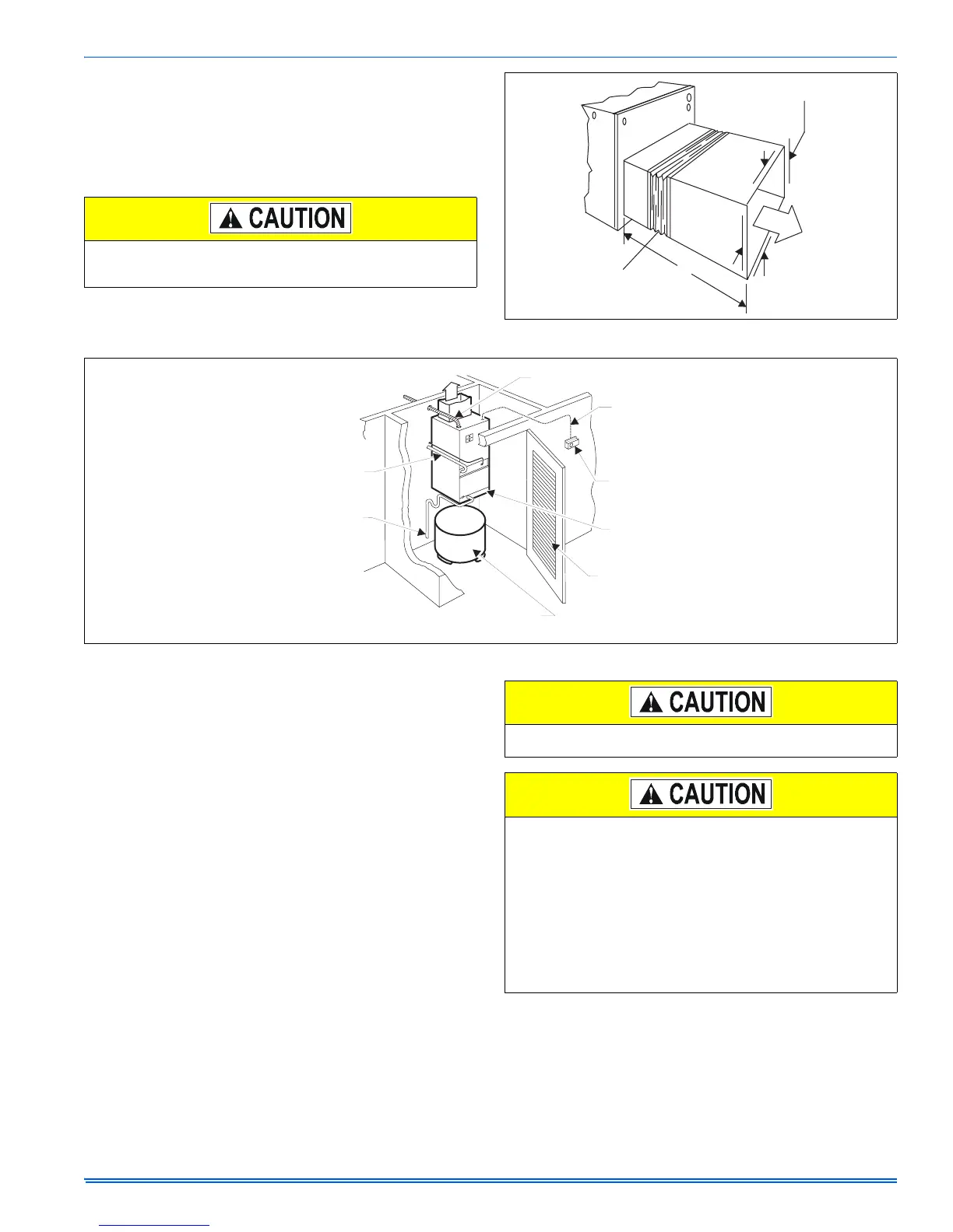
FIGURE 2: Typical Installation
POWER WIRING
TO MAIN
POWER SOURCE
SUPPLY
AIR
POWER WIRING
CONTROL
WIRING
THERMOSTAT
FILTER
ACCESS
LOUVERED
TO
CONDENSATE
DRAIN
REFRIGERANT
LINES
ELECTRIC HOT WATER HEATER
(Must comply with water heater installation instructions)
DO NOT TRY TO KNOCK OUT PANEL OPENING FOR SECOND-
ARY DRAIN PAN. SEE ITEM 7.
Models F*FP045,048,060 have a coil baffle and support bracket
factory installed for right hand horizontal application (refer to Figure
3C). For left hand applications the coil support bracket must be
moved to the right side of the coil, and the coil baffle must be
rotated to avoid water blow-off.
To rotate baffle, remove the coil assembly from the unit (remove
front two screws holding the coil support bracket and the two
screws holding the drain pan). Remove four screws in coil baffle
and remove the coil baffle and rotate ends.
Resecure the baffle and reinstall the coil assembly ensuring that
the rear of the drain pan is secured under the back flange of the
unit. Reinstall the coil support bracket on the right side of the coil.
 Loading...
