404912-UIM-A-0508
Johnson Controls Unitary Products 5
DUCT CONNECTIONS
NOTE: The electric heat accessory should be installed before the sup-
ply air duct is attached to the supply air openings. Refer to the electric
heater kit instructions for proper installation.
Air supply and return may be handled in one of several ways best
suited to the installation. See Figure 4 for dimensions for duct inlet and
outlet connections.
The vast majority of problems encountered with combination heating
and cooling systems can be linked to improperly designed or installed
duct systems. It is therefore highly important to the success of an instal-
lation that the duct system be properly designed and installed.
Use flexible duct collars to minimize the transmission of vibration/noise
into the conditioned space. If electric heat is used, non-flammable
material must be used.
Where return air duct is short, or where sound may be a problem,
sound absorbing glass fiber should be used inside the duct. Insulation
of duct work is a must where it runs through an unheated space during
the heating season or through an uncooled space during the cooling
season. The use of a vapor barrier is recommended to prevent absorp-
tion of moisture from the surrounding air into the insulation.
The supply air duct should be properly sized by use of a transition to
match unit opening. All ducts should be suspended using flexible hang-
ers and never fastened directly to the structure. This unit is not
designed for non-ducted (freeblow) applications. Size outlet plenum or
transition to discharge opening sizes shown in Figure 4.
Duct work should be fabricated and installed in accordance with local
and/or national codes. This includes the standards of the National Fire
Protection Association for Installation of Air-Conditioning and Ventilat-
ing Systems, NFPA No. 90B.
AIR FILTERS
Air filters must be field supplied. A 1" filter access rack has been built
into the unit. See Figure 4. Remove filter access cover shown. Install
proper size filter. Standard 1" size permanent or throw away filter may
be used, or, permanent washable filters are available using model num-
bers: 1PF0601, 602, 603BK. See Table 3 for filter size.
SUSPENSION KITS
A suspension kit is available. Models 1BH0601 (unit sizes 018-060) is
designed specifically for the units contained in this instruction (upflow
application only). For installation of these accessory kits, see the
instructions packed with the kit.
For suspension of these units in horizontal applications, it is recom-
mended to use angle steel support brackets with threaded rods, sup-
porting the units from the bottom, at the locations shown in Figure 5.
COIL METERING DEVICES
The coil in this Air Handler unit will have a TXV metering device
installed at the factory.
Air Handlers can be ordered with an R-22 TXV factory installed which
can be easily converted to R-410A by changing the bolt-on TXV. Refer
to the TXV metering device section for installation notes.
Air Handler “Flex-coils” are also available without a factory installed
metering device. For added application flexibility an orifice metering
device, R-22 TXV or R-410A TXV should be installed on the flex-coil in
the field to meet your refrigerant choice.
.
TXV Metering Device
Please refer to Table 2 to verify which TXV is installed in this Air Han-
dler unit and that this AHU is a valid system match for the AC or HP unit
installed.
Use 1/2" screws to connect ductwork to bottom of unit. Longer
screws will pierce the drain pan and cause leakage. If pilot holes
are drilled, drill only though field duct and unit bottom flange.
Equipment should never be operated without filters.
Units
(Nominal Tons)
Dimension
WW XX
018, 024, 030, 036, 040, 042 14” 40-3/4”
045, 048, 060 19-1/2” 50-3/4”
FIGURE 5: Typical Horizontal Installation
SUSPENSION SUPPORT LOCATIONS FOR HORIZONTAL APPLICATIONS*
2
WW
XX
1-1/2
NOTE: USE SUPPORTS UNDER UNIT.
TABLE 2:
Installed TXV Sizes
Indoor
Coil Model
Factory Installed
Metering Device
F4FP024H06T2A TXV 2A
F4FP024H06T2B TXV 2B
F4FP024H06T3X None
F4FP030H06T2A TXV 2A
F4FP030H06T3X None
F4FP036H06T2A TXV 2A
F4FP036H06T3X None
F4FP040H06T2A TXV 2A
F4FP040H06T2C TXV 2C
F4FP040H06T3X None
F4FP042H06T2A TXV 2A
F4FP042H06T2C TXV 2C
F4FP042H06T3X None
F4FP045H06T2C TXV 2C
F4FP045H06T3X None
F5FP048H06T2C TXV 2C
F5FP048H06T3X None
F5FP060H06T2C TXV 2C
F5FP060H06T3X None
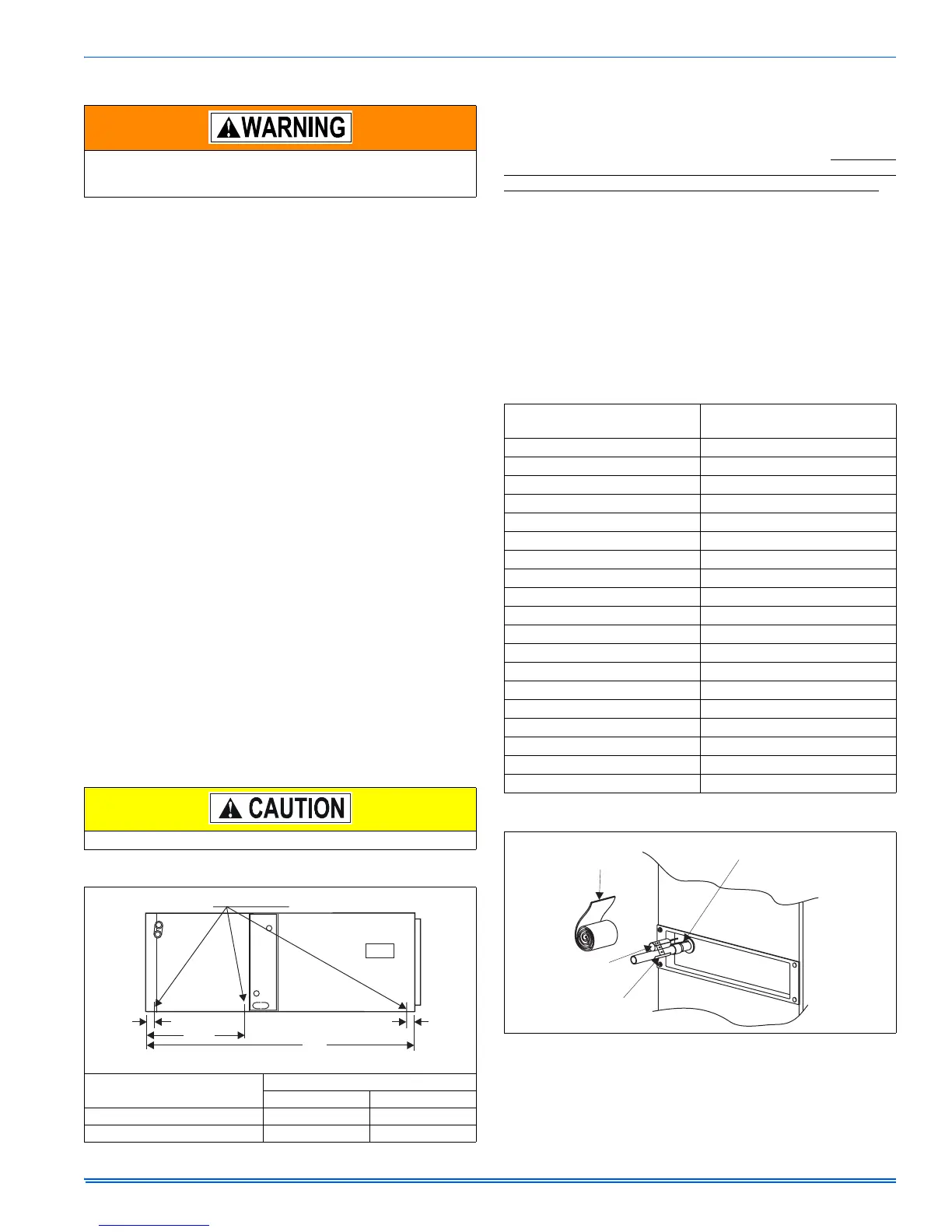
FIGURE 6: TXV Bulb Installation
INSULATION
ROLL
EXPANSION
BULB
EXPANSION
BULB CLAMP
EXPANSION
BULB TUBING
 Loading...
