FORM 160.54-M1(503)
157
YORK INTERNATIONAL
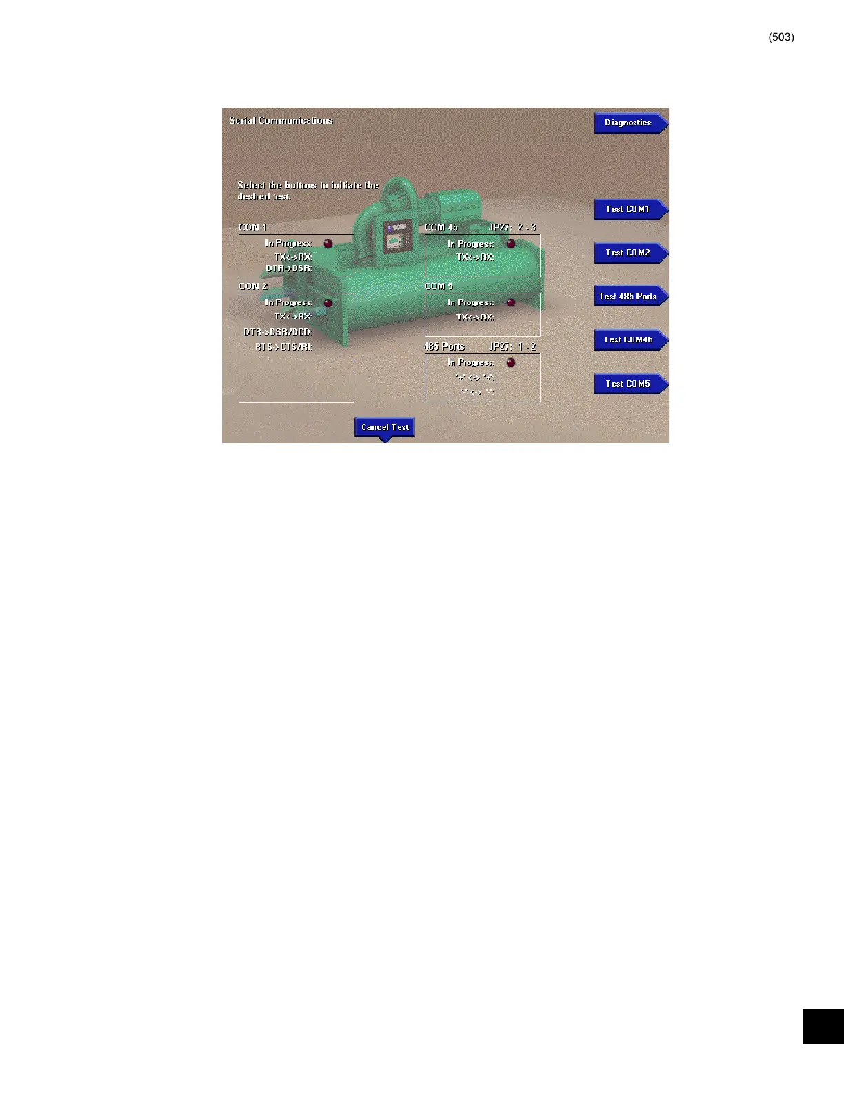
SERIAL INPUTS / OUTPUTS TESTS
FIG. 69 – SERIAL INPUTS / OUTPUTS TEST SCREEN
00339VIP
This diagnostic is used to verify correct op er a tion of the
Serial Data Ports. There is a test for each of the fi ve Serial
Data Ports. Each RS-232 port (COM 1, 2 and 4b) is tested
by transmitting serial test data from out puts to inputs of
each port. Both the transmit and re ceive func tions as well
as the control lines are tested. The RS-485 ports (COM
3 and 4a) are tested by trans mit ting serial test data from
one RS-485 port to an oth er. The TX/RX opto-coupled
port (COM 5) is tested by trans mit ting se ri al test data
from the TX output to the RX input. If the received data
matches the transmitted data, PASS is dis played, indicat-
ing the serial port is OK. Oth er wise, FAIL is displayed,
indicating the se ri al port is defective. Prior to perform-
ing each test, the Service Technician must in stall a wire
loop-back connection as described below. Refer to Sec-
tion 3 and Fig ure 11 of this book for de scrip tion of the
Serial data Ports.
PROCEDURE
1. Using small gauge wire, fabricate loop-back con-
nec tions and install as follows for each port to be
tested. Failure to install the loop-back connection
or confi gure the Microboard Program jumper as
noted will result in a FAIL outcome for the test.
From To
COM 1 J2-4 (TX) J2-3 (RX)
J2-5 (DTR) J2-2 (DSR)
From To
COM 2 J13-5 (TX) J13-3 (RX)
J13-7 (DTR) J13-1(DCD) & J13-2 (DSR)
J13-4 (RTS) J13-6 (CTS) & J13-8 (RI)
RS-485 From To
(COM J12-3 (+) J11-3 (+)
3 & 4a) J12-2 (-) J11-2 (-)
Microboard Program Jumper JP27 must be in stalled
in position 1 & 2.
From To
COM 4b J2-7 (GTX) J2-6 (GRX)
Microboard Program Jumper JP27 must be in stalled
in position 2 & 3.
From To
COM 5 J15-1 (TX) J15-4
J15-2 (RX) J15-5
J15-3 (Common) J15-6
Make individual wire connections or use YORK loop-
around diagnostic connector 025-33778-000 as de pict ed
in Figure 68 This connector is available from the YORK
Parts Distribution Center.
24
 Loading...