FORM 160.54-M1(503)
63
YORK INTERNATIONAL
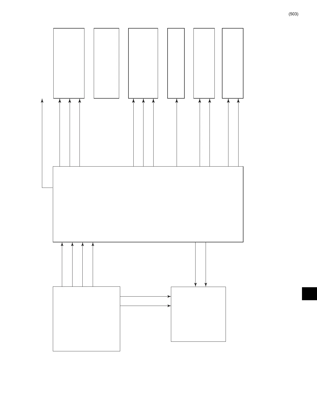
FIG. 35 – POWER SUPPLY – DC POWER DISTRIBUTION (REFER TO OPTIVIEW CONTROL CENTER WIRING DIAGRAM FOR WIRE CON NEC TIONS)
NOTES:
1. +5 or +3.3VDC as determined by Microboard Program Jumper JP2
& display requirements.
2. +12 or +5VDC as determined by Microboard Program Jumper JP5 &
display requirements.
3. Not Applicable to VSD or Mod “B” Solid State Starter applications.
4. Applications - CM2 (Em Starter), Logic Board (Mod “A” Solid State
Starter), Logic/Trigger Board (Mod “B” Solid State Starter), Adap tive
Ca pac i ty Con trol (VSD).
5. Refer to Fig. 45, 46 & 47 for Proximity Probe Power Connections. (Not
applicable to “P” compressors and style F and later chillers with “G”
and “H5-8” compressors)
LD06509
9
DC
POWER
SUPPLY
(NOTE 4)
CM-2 BOARD
or
SOLID STATE
STARTER LOGIC
BOARD
or
ACC BOARD
MICROBOARD
MICROGATEWAY
PROXIMITY
PROBE
(NOTE 5)
I/O
BOARD
OIL PUMP
VSD
LCD
DISPLAY
DISPLAY BACKLIGHT
INVERTER BOARD
+5VDC (ANALOG)
ALL TRANSDUCERS & THERMISTORS
+5VDC
+12VDC
GND
+5VDC
+12VDC
GND
VDD (NOTE 1)
GND
+V (NOTE 2)
GND
+12VDC
- 12VDC
+12VDC
GND
+5VDC
+5VDC (ANALOG)
GND (NOTE 3)
(NOTE 3)
+24VDC
GND
 Loading...