18 YORK INTERNATIONAL
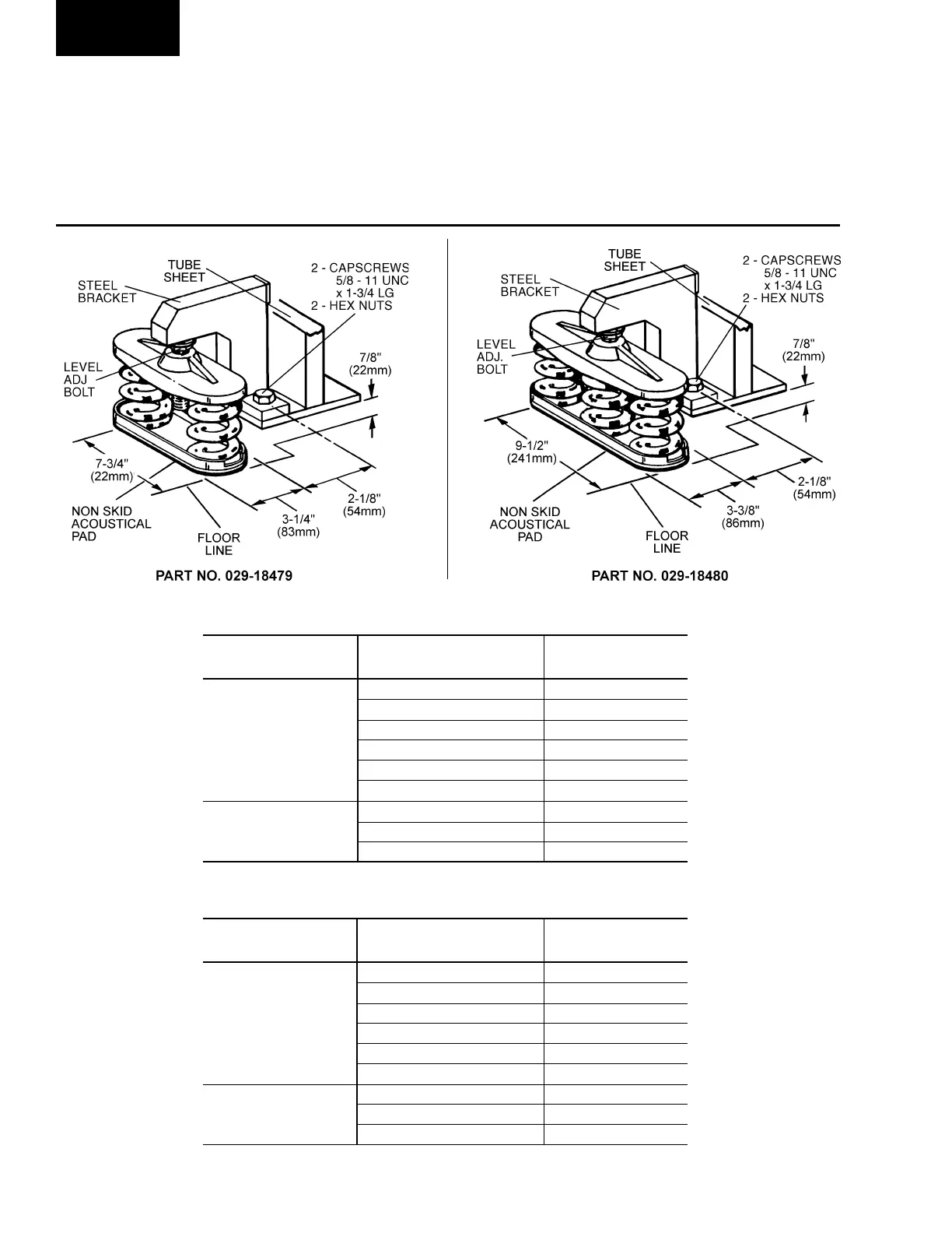
INSTALLING OPTIONAL SPRING ISOLATORS
To install these spring isolators, first remove the bolts
and nuts from the spring isolator bracket. Bolt the isola-
tor bracket to the unit foot support before the unit is
located on the floor. Place the four spring isolators in
position in accordance with the product drawing, Form
160.47-PA1. The threaded adjusting bolts in each isola-
tor should be screwed out of the isolator until the ex-
tended head of the screw fits snugly into the isolator
bracket hole. Then the unit is lowered over the adjust-
ing bolts. Refer to Figure 8.
FIG. 8 – SPRING ISOLATORS (OPTIONAL)
LD02946A
LD02947A
SPRING ISOLATORS (4 Per Unit) – ENGLISH
COMPRESSOR SYSTEM OPERATING
PART NO.
SIZE WEIGHT (Lbs.)
UP to 6,865 029-18479-001
6,866 to 9,818 029-18479-002
S0, S1, 9,819 to 12,182 029-18479-003
S2, S3 12,183 to 15,272 029-18479-004
15,273 to 18,272 029-18480-001
18,273 to 22,909 029-18480-002
UP to 22,909 029-18480-002
S4, S5 22,910 to 26,044 029-18480-003
26,045 to 32,101 029-18480-004
SPRING ISOLATORS (4 Per Unit) – SI
COMPRESSOR SYSTEM OPERATING
PART NO.
SIZE WEIGHT (mm)
UP to 3,114 029-18479-001
3,115 to 4,453 029-18479-002
S0, S1, 4,454 to 5,525 029-18479-003
S2, S3 5,526 to 6,927 029-18479-004
6,928 to 8,288 029-18480-001
8,289 to 10,392 029-18480-002
UP to 10,392 029-18480-002
S4, S5 10,392 to 11,813 029-18480-003
11,814 to 14,561 029-18480-004
Installation
 Loading...


