37
FORM 160.47-NOM3
YORK INTERNATIONAL
CAPACITY CONTROL
Refer to the Capacity Control Piping Schematic piping,
figure 23.
Evaporator fluid Set Point. When the leaving evapora-
tor fluid temperature is beyond the range of the set point
value a signal is sent to the relay output board. A signal
is sent from the relay output board to energize the 4-
way valve directional solenoid valves.
When Solenoid Valve B is energized the slide valve be-
gins to move in the load direction. The 4-way direc-
tional valve opens Port P to Port B and Port A to Port T.
Oil pressure from the oil circuit flows into the 4-way
solenoid valve sub-plate manifold at Port P. Oil pres-
sure flows through the sub-plate manifold block and out
Port B to Compressor Port SC-2. Simultaneously, oil
flows out of Compressor Port SC-1 into Port A on the
sub-plate manifold, through the sub-plate manifold block
and out of the sub-plate manifold block at Port T to
suction pressure.
When the Solenoid Valve A is energized, the slide valve
will move in the unload direction. The 4-way directional
valve opens Port P to Port A and Port B to Port T. See
Figure 24. High pressure oil flows into Compressor Port
SC-1 and oil is relieved out of Compressor Port SC-2 to
suction pressure.
A slide valve potentiometer is used to provide feedback
to the microprocessor to display slide valve position as
a percentage of full load.
Four manual isolation valves are incorporated into the
4-way solenoid sub-plate to isolate the 4-way directional
valve for service. Remove the steel hexagonal caps to
gain access to the service valve stem. Use a refrigera-
tion service valve wrench to close or open the valves.
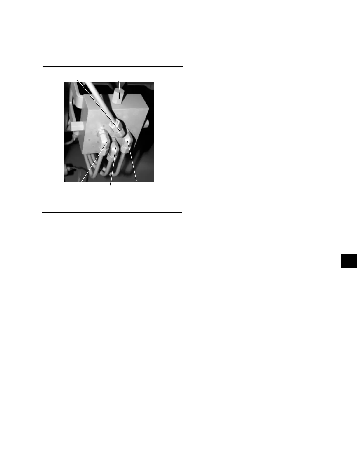
FIG. 24 – 4-WAY DIRECTIONAL VALVE SUBPLATE
2
Capacity control is accomplished by using differential
pressure to move the slide valve. As the slide valve is
moved axially between the compressor rotors the vol-
ume of gas pumped by the compressor is changed to
match the system requirements.
Leaving evaporator fluid temperature is continuously
monitored by the microprocessor. The Leaving Evapo-
rator fluid temperature is compared to the Leaving
SERVICE ISOLATION
VALVE CAP
PORT “T”
PORT “A”
PORT “P”
PORT “B”
2

 Loading...


