5167540-YIM-H-0518
Johnson Controls Ducted Systems 19
Thermostat Wiring
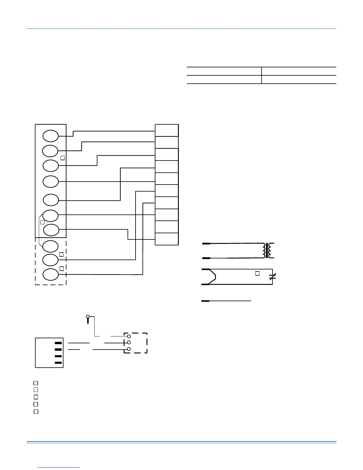
A two stage thermostat must be used and should be located on
an inside wall approximately 56 inch above the floor where it will
not be subject to drafts, sun exposure or heat from electrical
fixtures or appliances. Follow the manufacturer's instructions
enclosed with thermostat for general installation procedure.
Color-coded, insulated wires should be used to connect the
thermostat to the unit. Refer to Table 8 for control wire sizing
and maximum length.
Figure 22: Typical Low Voltage Field Wiring
Table 8: Control Wire Sizes
Wire Size Maximum Length
1
1. From the unit to the thermostat and back to the unit.
18 AWG 150 Feet
OCC
C
RC
G
Y2
Y1
W2
W1
X
R
THERMOSTAT
TERMINALS
CONTROL
TERMINAL
BLOCK
TERMINALS ON A
LIMITED NUMBER
OF THERMOSTATS
1
4
3
1
4
Second stageŚĞĂƟŶŐŶot required on single stage heĂƟŶg units.
Jumper is required for any coŵďŝŶĂƟŽŶ of R, RC, or RH.
5
5
OCC is an output from the thermostat to indicate the Occupied ĐŽŶĚŝƟon.
X is an input to the thermostat to display Error Status condiƟons.
3
W2
Y1
G
OCC
Y2
X
R
SD-24
C
W1
24V
COM
OUT
Return or Space Humidity
Sensor (0-10VDC)
TB4-3
823/R
-
+
+
RAH
DCT
PRS
-
P4
1)
2)
3)
4)
825/W
824/BK
S4
24V
C
24 VAC
Class 2
SD-24
Jumper Located on Harness
Smoke
Detector
SD-R
24V Output
R
(If No Smoke Detector)
(If Smoke Detector Is Used)
2
Jumper is required if there is no Smoke Detector circuit.
2
 Loading...