5167540-YIM-H-0518
48 Johnson Controls Ducted Systems
Reheat Mode Sequence Of Operation
The MagnaDRY reheat mode of operation is designed to
remove latent heat (Humidity) from a space when there are low
load conditions and the air conditioning unit is not being
required to cool the space. The general sequence of operation
of the patented MagnaDRY reheat is outlined in the following
paragraphs.
When the Unit Control Board (UCB) detects a need for
dehumidification via the field installed return/space humidity
sensor and there is not a call for cooling, the UCB energizes
solenoids SOL 3 (HGRH), SOL 2 and the Reheat Relay (RHR),
which de-energizes SOL 1. The unit then operates with
refrigerant flow in the evaporator reheat coil and condenser coil
#1. See Figure 29.
When there is a call for the first stage of cooling while there is
still a call for dehumidification, no operational change is made.
The call for cooling is ignored and the unit continues to operate
with refrigerant flow in the reheat coil and condenser coil #1.
See Figure 29.
Indoor blower operation is initiated upon a call for first stage
cooling, second stage cooling or dehumidification. Anytime
there is a call for a second stage of cooling, the unit will not
operate in the reheat mode, even if there is still a call for
dehumidification. The unit will not operate in the reheat mode if
there is any call for heating. All safety devices function as
previously described in this document. See Figure 30.
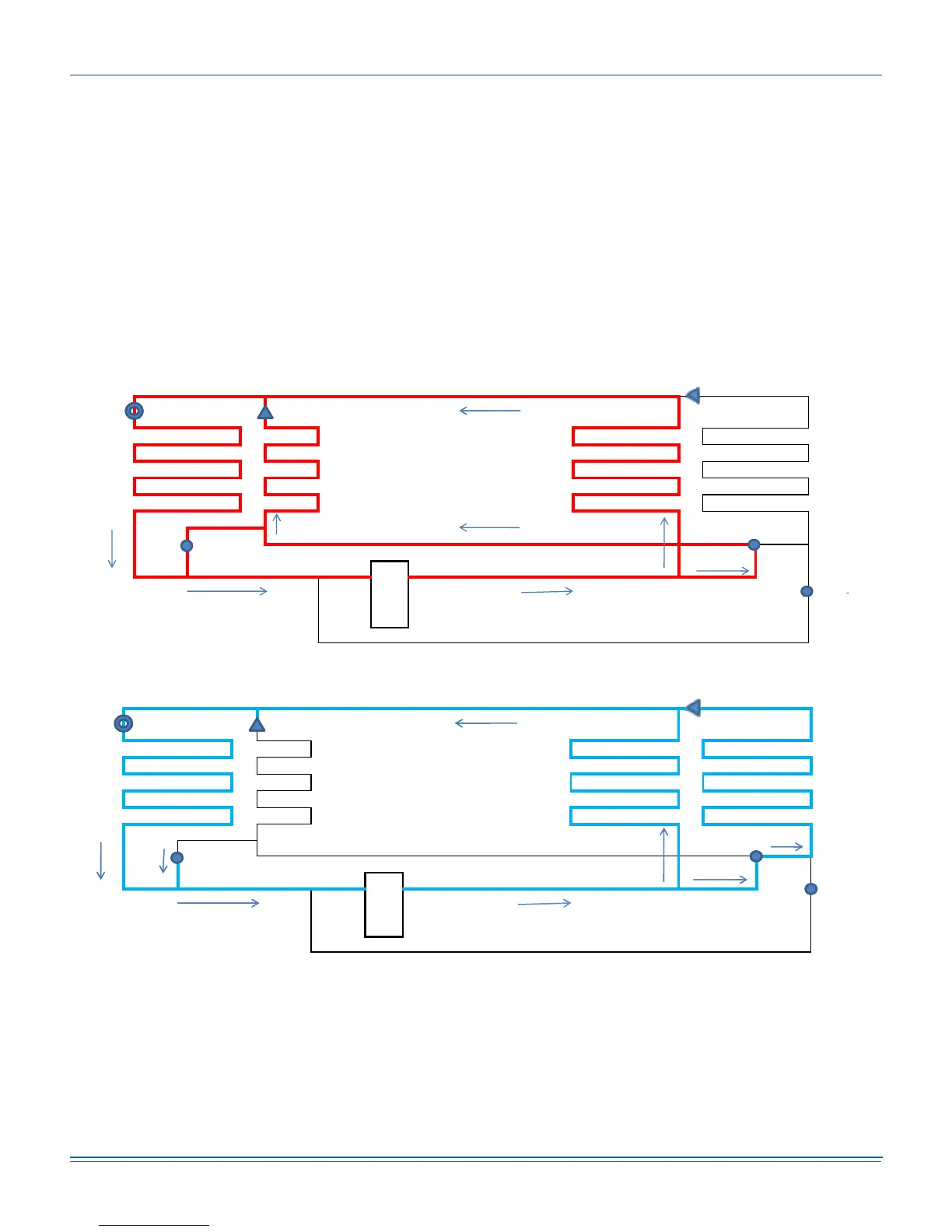
Figure 29: Reheat Operation Piping Schematic
Figure 30: Cooling Operation Piping Schematic
Reheat kcehCnoitarepO
TXV Check Valve
Valve
--------> -------->
Indoor Outdoor
.dnoC.dnoCriAtaeheR.pavEriA
lioCwolFlioClioCwolF 1 Coil 2
--------> -------->
Closed
HGRH Valve
^ƵĐƟŽn Discharge
Comp. OPEN
Recovery
Valve SOL #2
Recovery
Valve SOL #1
SOL #3
Cooling kcehCnoitarepO
TXV Check Valve
Valve
--------> -------->
Air .dnoCtaeheR.pavEwolF Fan Cond. Cond.
--------> Coil Coil --------> Coil 1 Coil 2
OPEN SOL #3
HGRH Valve
SucƟon Discharge
Comp.
CLOSED
Recovery
Valve SOL #2
Recovery
Valve SOL #1
 Loading...