JOHNSON CONTROLS
171
SECTION 8 – UNIT OPERATION
FORM 150.67-NM2
ISSUE DATE: 01/31/2019
8
YCAL0043 – 0066 LOW AMBIENT FAN
CONTROL OPTION
General
The low ambient option consists of a VFD (Variable
Frequency Drive) for each system that controls the
speed of the rst fan (Fan 1, Sys #1 or Fan 2, Sys # 2)
in the fan staging sequence. The VFD’s are located in
an enclosure in the compressor/piping/heat exchanger
section on (2) compressor chillers. System # 1 VFD
is located on the bottom and System # 2 is on the top.
Single system chillers have the VFD installed on the
top of chiller above the compressor section. Examples
of the typical VFD location and enclosure mountings
are shown in Figure 54 on page 171 and Figure 55 on
page 172.
The VFD will control fan speed when only a single
fan is running on a system. As discharge pressure ris-
es, the fan speed will be increased from zero RPM to
full speed. As discharge pressure continues to rise, the
VFD will operate the fan at full speed and the second
fan will be brought on in a system, if needed. When-
ever the second fan is brought on, the inverter will al-
ready be running the first fan at full speed.
If discharge pressure falls, the chiller microprocessor
will turn the second fan off by de-energizing the fan
contactor. If pressure continues to fall, VFD speed will
decrease in an effort to maintain discharge pressure.
Speed may drop to the point where the VFD turns the
fan completely off or virtually off with a continued
drop in pressure.
The VFD control input signal is from the discharge
pressure transducer in the respective system. The
transducer signal feeds both the chiller microprocessor
board input and the VFD.
The VFD will control the fan speed not only in low
ambient conditions, but in all ambients based on dis-
charge pressure. Speed control of the respective sys-
tem will occur whenever high voltage power is applied
to the VFD power inputs through the 7M (Sys 1) or
10M (Sys 2) contactors. The chiller microprocessor
will energize the 7M and 10M contactors whenever
the respective system liquid line solenoid is energized.
The VFD controls the speed of the fan based on a
discharge pressure setpoint and a differential con-
trol range. When a compressor starts in a system, the
inverter is activated through the 7M (Sys 1) or 10 M
(Sys 2) contactor, which is controlled from the respec-
tive liquid line solenoid valve control signal. At dis-
charge pressures below 260 PSIG, the VFD will turn
the fan off or speed will be reduced to small move-
ments in fan rotation.
The pressures indicated in this section
describing the VFD control will vary from
VFD to VFD. Expect tolerances for the
entire pressure range of control to poten-
tially shift -0 PSIG/+24 PSIG.
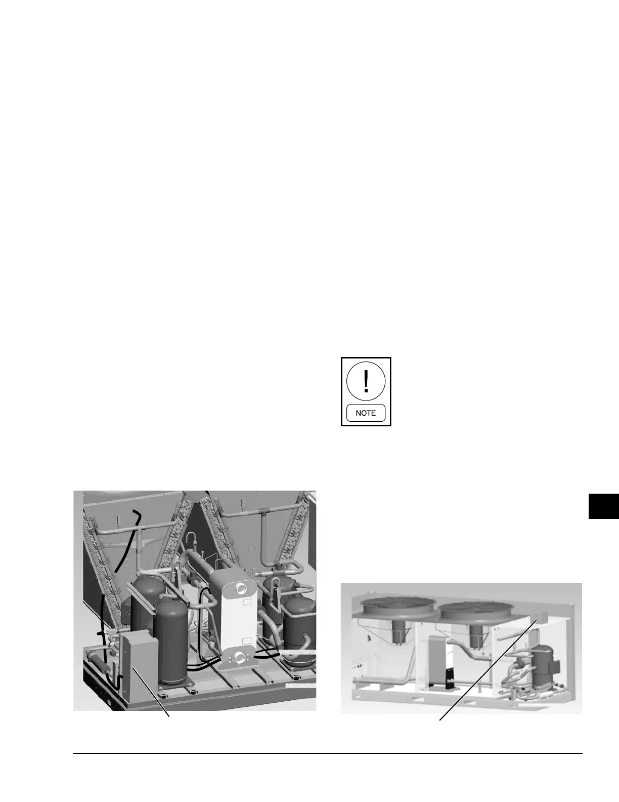
Single System VFD Enclosure Location
LD12080
FIGURE 54 - TYPICAL VFD ENCLOSURE LOCATIONS
Dual System VFD Enclosure Location
LD11298
 Loading...

