76 YORK INTERNATIONAL
FORM 201.18-NM1 (102)
MI
R
MP
TE
NTR
L
ENTE
PTI
N
PANE
1
NTR
TRAN
F
RME
ERVI
E
WIT
1-7/8
EDGE O
NIT T
LE
CONNECTION
1-
P
WER
PENIN
7-3/4" WIDE x
9-1/2")
Technical Data
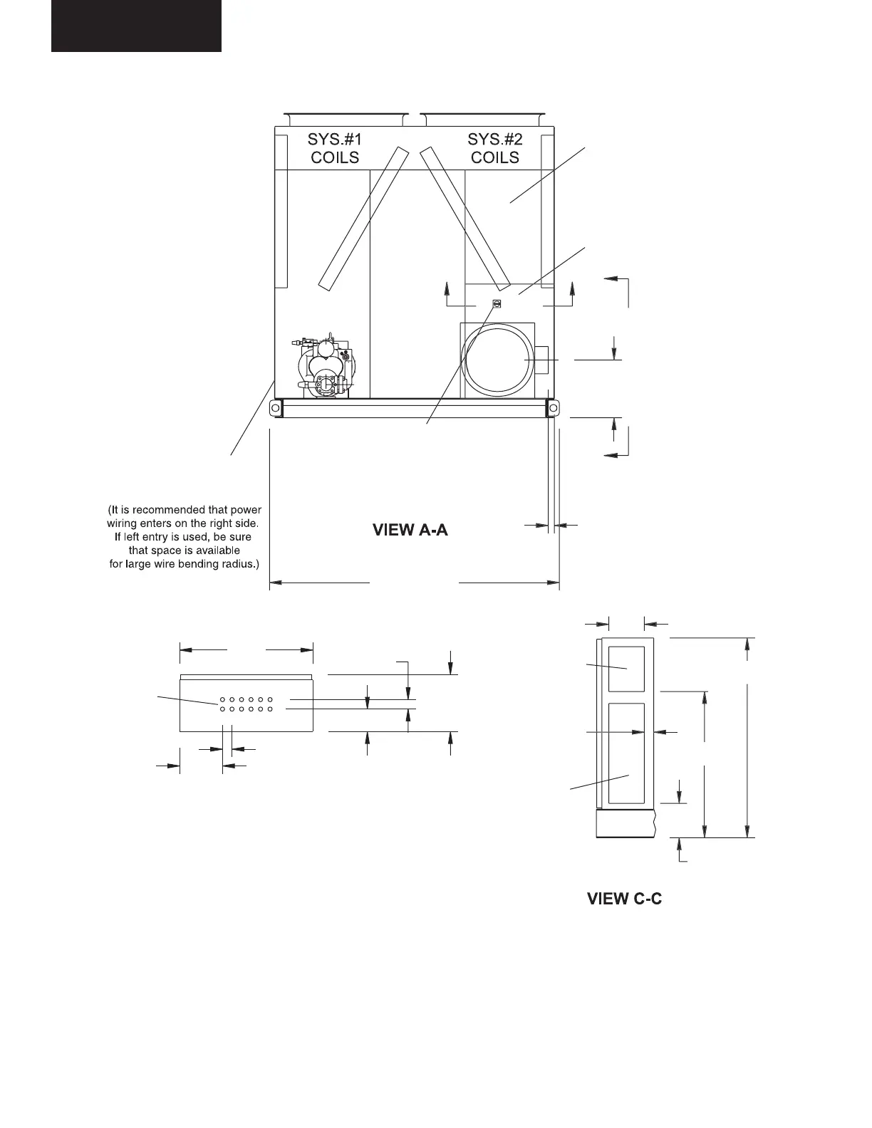
DIMENSIONS - YCAS0200 - 0230 (ENGLISH)
FIG. 34 – MODEL 0200 - 0230 DIMENSIONS (ENGLISH DIMENSIONS)
CONTROL ENTRY
(12) 7/8" DIA.
KNOCKOUTS
8-7/8"
VIEW B-B
2" TYP.
28"
2"
4-3/4"
12"
LD02996
7-1
2
-
4
7-1
4
NTR
PENIN
9-1/2" HIGH
P
WE
PENIN
21" HIGH
LD02997
LD02998
NOTES:
1. Placement on a level surface free of obstructions (including snow, for winter operation) or air
recirculation ensures rated performance, reliable operation and ease of maintenance. Site re-
strictions may compromise minimum clearances indicated below, resulting in unpredictable air
flow patterns and possible diminished performance. YORK’s unit controls will optimize operation
without nuisance high pressure safety cutout; however, the system designer must consider po-
tential performance degradation. Access to the unit Micro Panel assumes the unit is no higher
than on spring isolators. Recommended minimum clearances: Side to wall - 6'; rear to wall - 6';
control panel end to wall - 4'; top - no obstructions allowed; distance between adjacent units - 10'.
No more than one adjacent wall may be higher than the unit.
 Loading...