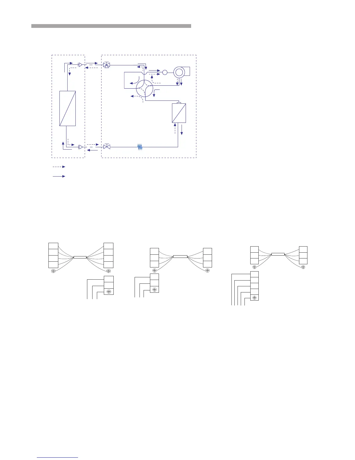
Diagram of refrigerant cycle & Wiring
1. REFRIGERANT FLOW DIAGRAM
2. ELECTRICAL WIRING DIAGRAM
8
Indoor unit
Power supply
Power supply
Power supply
Outdoor unit
Indoor unit
Terminal
Terminal
SI
L
N
SI
L
N
Power connecting cord
N
L
Outdoor unit
Terminal Terminal
SI
L
N
SI
L
N
Power connecting cord
N
R
S
T
36K/48K/55K
Outdoor unit
Indoor unit
Terminal Terminal
N
N
1L
3L
2L
1L
3L
2L
Power connecting cord
N
L
18K
24K
Gas piping
Wide service valve
Compressor
Accumulator
4-way valve
Heat exchanger
Liquid piping
Heating cycle
Cooling cycle
INDOOR UNIT OUTDOOR UNIT
Heat exchanger
Service valve
Note:
Accumulator is only applicable to 48k and 60k air-conditioners.
capillary tube
AUV-18HR4SSA1
AUV-24HR4SFA1
AUV-36HR6SDB1
AUV-48HR6SEC1
AUV-60HR6SPC1
RPFC-2.0UNZ1NH
RPFC-3.0UNZ1NH
RPFC-4.0UNZ1NH
RPFC-6.0UNZ1NH
RPFC-6.5UNZ1NH
YFGN18BZNRZUH1
YFGN24BZNRZUH1
YFGN36BZMRZUH1
YFGN48BZMRZUH1
YFGN55BZMRZUH1
RAS-2.0UNZGNH1
RAS-3.0UNZGNH1
RAS-4.0UNZGMH1
RAS-6.0UNZGMH1
RAS-6.5UNZGMH1
●
Blowing out the surviwal heating air
When stoping the air conditioner in normal operation, the fan motor would run with low speed for a while to blow
out the residual heating air.
 Loading...