10.5 Electrical Installation
● Use an ELB (Electric Leakage Breaker). If not used, it might cause an electric shock or a fire.
● Do not operate the system until all the check points have been cleared.
(A) Check to ensure that the insulation resistance is more than 2 , by measuring the MΩ
resistance between ground and the terminal of the electrical parts. If not, do not operate the
system until the electrical leakage is found and repaired.
(B) Check to ensure that the stop valves of the outdoor unit are fully opened and then start the
system.
NOTES:
1) Follow local codes and regulations when selecting field wires.
2) The wire sizes marked in the table are selected at the maximum current of the unit according to the
European Standard, EN60335-1. Use the wires which are not lighter than the ordinary polychloroprene
sheathed flexible cord (code designation H07RN-F).
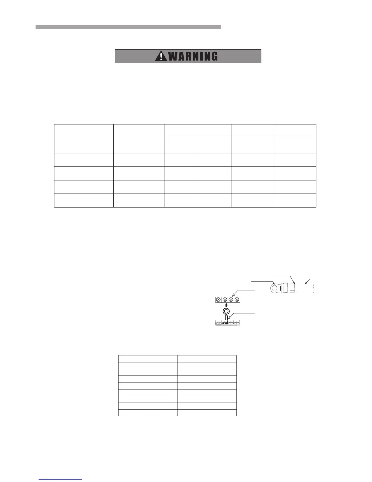
When connecting the terminal block using flexible cord, make sure to use the round crimp-style terminal
for connection to the power supply terminal block.
Place the round crimp-style terminals on the wires up to the covered
part and secure in place.
When connecting the terminal block using a single core
wire, be sure to perform curing.
3) When transmitting cable length is more than 15 meters, a larger wire size should be selected.
4)Use a shielded cable for the transmitting circuit and connect it to ground.
Flexible cord
covered part
Round crimp-style terminal
Terminal
Single core wire
5)In the case that power cables are connected in series, add each unit maximum current and select
wires below.
*In the case that current exceeds 63A, do not connect cables in series.
6)To be in compliance with EN 61000-3-3, the product shall be connected only to a supply of the system
impedance:Zsys≤0.27Ω(18Κ), Zsys≤0.123Ω (24Κ). Before connecting the product to public power network,
please consult your local power supply authority to ensure the power network meet above requirement.
 Loading...