18
Installation and Maintenance
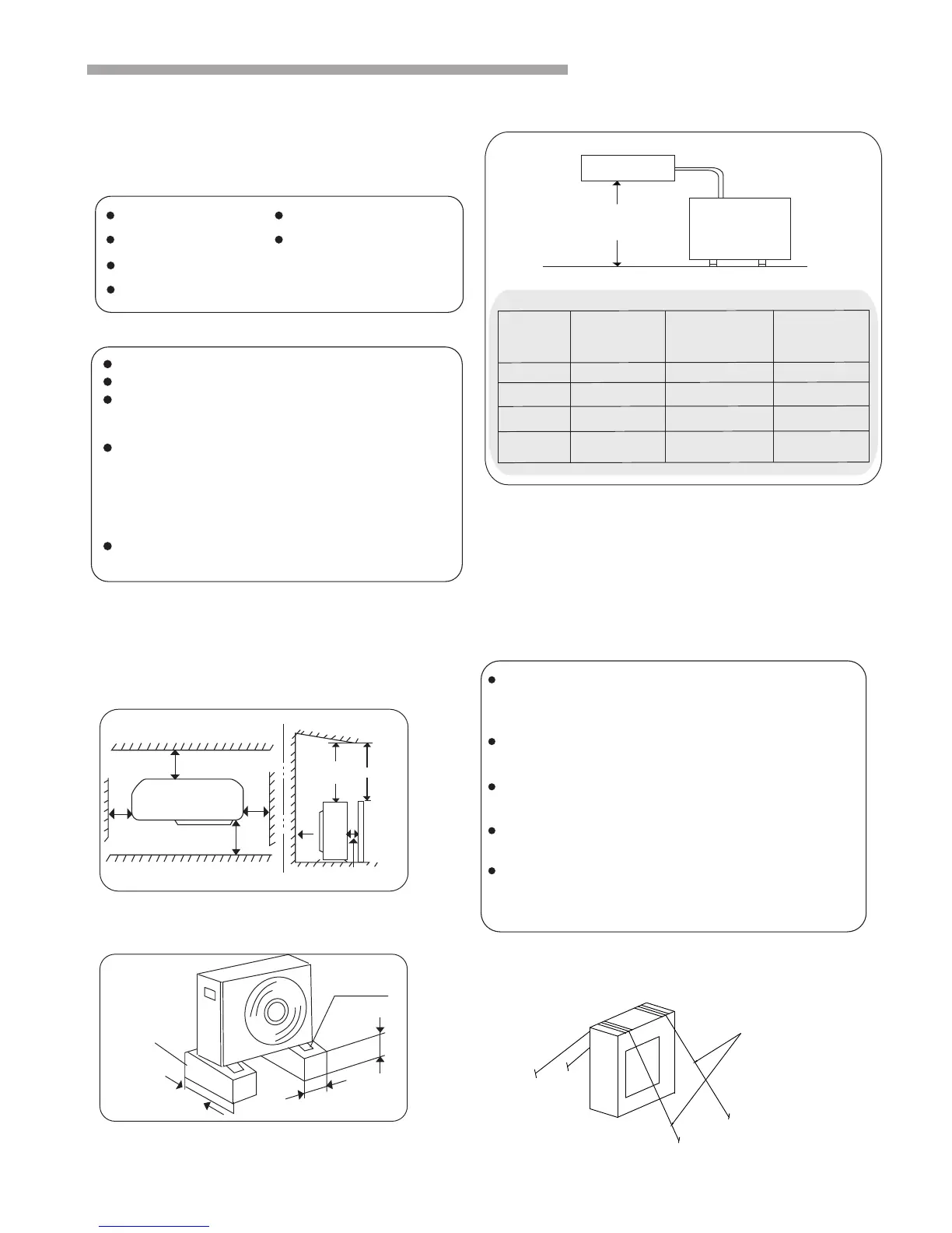
8. The Installation of the Outdoor Unit
Avoid
Direct sunlight
Near Heat Source/ventilation fan
Container With Flammable materials
Thick Oil fog
Wet Or Uneven place
Aisle Or sideway
8.1 Installation sites
Place it in cool temperature.
Place it in an area with good ventilation.
Have desired space for air inlet, outlet and
maintenance. (Fig. 8.1)
2
Make a strong base(10X40cm board made of
concrete or similar). The appliance should be placed
not less than 10 cm high to avoid being wet or
corroded. Otherwise, it may cause damage to the
appliance or reduce its life time. (Fig. 8.2)
Fix the base with hook bolts or alike to reduce
vibration and noise.
You should
If the total tube length is between 5m and 50m (Max.
length), an additional refrigerant must be added. It's not
necessary to add compressor oil.(Fig. 8.3)
Fig. 8.2
Fig. 8.3
Obstacle
Top obstacle
Air outlet
2m
2m
Ground
Min.10cm
Air inlet
Min. 10cm
Min.
10cm
Air outlet
Air inlet
Min.
35cm
Min.40cm
Fig. 8.1
Min.10cm
Setscrew
(at least 4)
About 40cm
About 10cm
Indoor unit
Tube length L
Height difference H
Outdoor unit
20(m) 15(m) 15(g/m)
30(m) 15(m) 35(g/m)
30(m) 20(m) 35(g/m)
50(m) 30(m) 35(g/m)
Max. Tube
length(L)
Model
24K
36K
48K/
55K
18K
Max. Height
difference(H)
Add.
Refrigerant
(exceed 5m)
8.2 Installation of the Outdoor Unit
Firstly select the installation site and fix the outdoor
unit. If it needs to be fixed onto the wall, make sure
that the wall and the supporting rack is strong enough
to hold the weight of the appliance.
Wiring instruction for outdoor unit
Wire Ropes
●Fix the unit with wire ropes to prevent overturning
in case a seasonal strong wind(storm, etc.)
blows against the unit .
Concrete base or similar
Release the setscrews of the electric cover,
remove the electric cover (If the valve cover is
there either, please release it).
Connect the indoor unit wiring to the outdoor unit
panel according to the electric wiring diagrams.
Be sure to make each wire allowing 10cm longer
than the required length for wiring.
Ground the unit following local electrical
regulations.
Check the wiring with the wiring diagrams and
make sure it's well connected. Fix the wiring with
clips and reinstall the electric cover.
Fig.8.4
AUV-18HR4SSA1
AUV-24HR4SFA1
AUV-36HR6SDB1
AUV-48HR6SEC1
AUV-60HR6SPC1
RPFC-2.0UNZ1NH
RPFC-3.0UNZ1NH
RPFC-4.0UNZ1NH
RPFC-6.0UNZ1NH
RPFC-6.5UNZ1NH
YFGN18BZNRZUH1
YFGN24BZNRZUH1
YFGN36BZMRZUH1
YFGN48BZMRZUH1
YFGN55BZMRZUH1
RAS-2.0UNZGNH1
RAS-3.0UNZGNH1
RAS-4.0UNZGMH1
RAS-6.0UNZGMH1
RAS-6.5UNZGMH1
●
Blowing out the surviwal heating air
When stoping the air conditioner in normal operation, the fan motor would run with low speed for a while to blow
out the residual heating air.
 Loading...