5464597-YIM-B-0518
46 Johnson Controls Ducted Systems
Airflow Performance
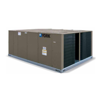
Table 16: Airflow Performance - Side Duct Application
ZF078 (6.5 Ton) Side Duct
Air Flow
(CFM)
Available External Static Pressure - IWG
1
1. Blower performance includes gas heat exchangers and 2” filters. See STATIC RESISTANCE table for additional applications.
2. See RPM SELECTION table to determine desired motor sheave setting and to determine the maximum continuous BHP.
3. kW = BHP x 0.932.
0.2 0.4 0.6 0.8 1.0 1.2 1.4 1.6 1.8 2.0
RPM BHP RPM BHP RPM BHP RPM BHP RPM BHP RPM BHP RPM BHP RPM BHP RPM BHP RPM BHP
Field Supplied Drive Standard 1.5 HP & Drive Hi Static 2 HP & Drive
1800 751 0.22 813 0.43 872 0.62 929 0.78 985 0.93 1040 1.07 1095 1.20 1150 1.33 1206 1.46 1265 1.59
2000 776 0.35 838 0.56 897 0.75 954 0.92 1010 1.07 1064 1.20 1119 1.33 1175 1.46 1231 1.59 1289 1.72
2200 804 0.50 866 0.71 925 0.90 982 1.06 1038 1.21 1092 1.35 1147 1.48 1203 1.61 1259 1.73 1317 1.87
2400 835 0.66 897 0.87 956 1.06 1013 1.22 1069 1.37 1124 1.51 1178 1.64 1234 1.77 1290 1.90 1348 2.03
2600 869 0.84 931 1.05 990 1.24 1047 1.40 1103 1.55 1158 1.69 1212 1.82 1268 1.95 1324 2.07 1382 2.21
2800 906 1.03 968 1.25 1027 1.43 1084 1.60 1139 1.75 1194 1.89 1249 2.02 1304 2.14 1361 2.27 - -
3000 945 1.25 1007 1.46 1066 1.65 1123 1.81 1179 1.96 1234 2.10 1288 2.23 - -----
3200 987 1.48 1048 1.69 1107 1.88 1165 2.04 1220 2.19 - - - - - -----
340010301.7310921.9411512.1212082.29------------
2 HP & Field Supplied Drive
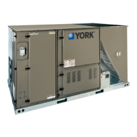
ZF090 (7.5 Ton) Side Duct
Air Flow
(CFM)
Available External Static Pressure - IWG
1
1. Blower performance includes gas heat exchangers and 2” filters. See STATIC RESISTANCE table for additional applications.
2. See RPM SELECTION table to determine desired motor sheave setting and to determine the maximum continuous BHP.
3. kW = BHP x 0.932.
0.2 0.4 0.6 0.8 1.0 1.2 1.4 1.6 1.8 2.0
RPM BHP RPM BHP RPM BHP RPM BHP RPM BHP RPM BHP RPM BHP RPM BHP RPM BHP RPM BHP
Field Supplied Drive Standard 1.5 HP & Drive Hi Static 3 HP & Drive
2000 776 0.35 838 0.56 897 0.75 954 0.92 1010 1.07 1064 1.20 1119 1.33 1175 1.46 1231 1.59 1289 1.72
2200 804 0.50 866 0.71 925 0.90 982 1.06 1038 1.21 1092 1.35 1147 1.48 1203 1.61 1259 1.73 1317 1.87
2400 835 0.66 897 0.87 956 1.06 1013 1.22 1069 1.37 1124 1.51 1178 1.64 1234 1.77 1290 1.90 1348 2.03
2600 869 0.84 931 1.05 990 1.24 1047 1.40 1103 1.55 1158 1.69 1212 1.82 1268 1.95 1324 2.07 1382 2.21
2800 906 1.03 968 1.25 1027 1.43 1084 1.60 1139 1.75 1194 1.89 1249 2.02 1304 2.14 1361 2.27 1419 2.40
3000 945 1.25 1007 1.46 1066 1.65 1123 1.81 1179 1.96 1234 2.10 1288 2.23 1344 2.36 1400 2.48 1458 2.62
3200 987 1.48 1048 1.69 1107 1.88 1165 2.04 1220 2.19 1275 2.33 1330 2.46 1385 2.59 1442 2.71 1500 2.85
3400 1030 1.73 1092 1.94 1151 2.12 1208 2.29 1264 2.44 1319 2.58 1374 2.71 1429 2.84 1485 2.96 1544 3.10
3600 1076 1.99 1138 2.20 1197 2.39 1254 2.56 1310 2.71 1364 2.84 1419 2.97 1475 3.10 1531 3.23 1589 3.36
3800 1124 2.27 1185 2.48 1245 2.67 1302 2.84 1357 2.99 1412 3.12 1467 3.25 1522 3.38 ----
3 HP & Field Supplied Drive
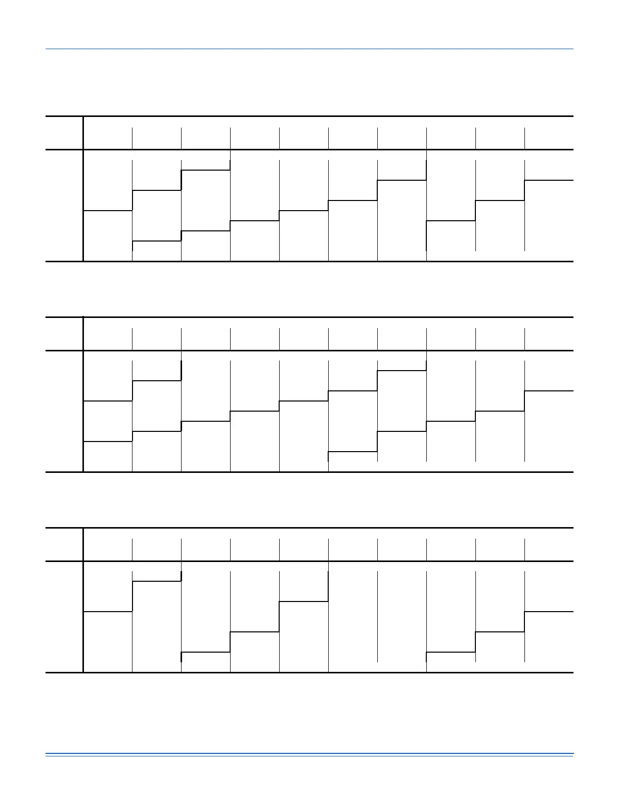
ZF102 (8.5 Ton) Side Duct
Air Flow
(CFM)
Available External Static Pressure - IWG
1
1. Blower performance includes gas heat exchangers and 2” filters. See STATIC RESISTANCE table for additional applications.
2. See RPM SELECTION table to determine desired motor sheave setting and to determine the maximum continuous BHP.
3. kW = BHP x 0.932.
0.2 0.4 0.6 0.8 1.0 1.2 1.4 1.6 1.8 2.0
RPM BHP RPM BHP RPM BHP RPM BHP RPM BHP RPM BHP RPM BHP RPM BHP RPM BHP RPM BHP
Field Supplied Drive Standard 2 HP & Drive Hi Static 3 HP & Drive
2600 628 0.56 678 0.76 730 0.93 781 1.09 833 1.25 883 1.41 933 1.59 980 1.80 1025 2.05 1068 2.35
2800 648 0.67 698 0.87 750 1.04 801 1.20 853 1.36 903 1.52 953 1.70 1000 1.91 1046 2.16 1088 2.46
3000 666 0.80 717 1.00 768 1.17 820 1.33 871 1.49 922 1.65 971 1.83 1019 2.04 1064 2.29 1106 2.59
3200 684 0.95 735 1.15 786 1.32 838 1.48 889 1.63 940 1.80 989 1.98 1037 2.19 1082 2.44 1124 2.74
3400 702 1.11 753 1.31 804 1.48 856 1.64 907 1.79 958 1.96 1007 2.14 1055 2.35 1100 2.60 1142 2.90
3600 721 1.28 772 1.48 824 1.65 875 1.81 927 1.97 977 2.13 1027 2.31 1074 2.52 1119 2.77 --- ---
3800 742 1.47 793 1.67 844 1.84 896 2.00 947 2.15 998 2.32 1047 2.50 1095 2.71 1140 2.96 --- ---
4000 765 1.67 815 1.86 867 2.04 918 2.19 970 2.35 1020 2.51 1070 2.70 1117 2.91 --- --- --- ---
4200 789 1.87 840 2.07 891 2.24 943 2.40 995 2.56 1045 2.72 1094 2.90 --- --- --- --- --- ---
3 HP & Field Supplied Drive

 Loading...