APPENDIX I
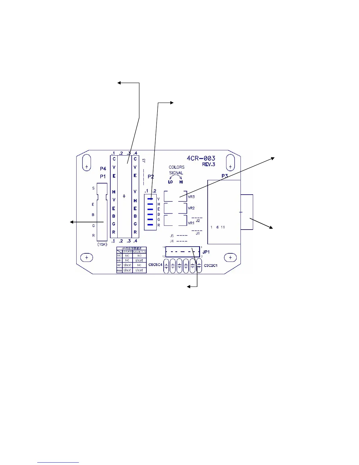
Signal Input Connector Board
- 13 -
Input:
z 6 in or 10 pin
connector for
America standard.
z 6 pin connector for
Europe standard.
COLORS
SIGNAL(VR1、
VR2、VR3):R、
G、B signal
decline
adjustment.
Input:
6 pin connector for
Japan standard.
Output:
15 pin D-Sub
male connector.
Input:
5 pin
connector
in common
use
.
JP1: filter and
eliminate noise.
1. In order to offer the user who has different types of connectors of the signal output,
we provide the available connectors, such as P1, P2 and P4. However, P3 is a male
connector which can be fixed directly on the LCD monitor (plug P3 on the
monitor, VGA IN connector) or use double female connector and plug in P3 in
order to match up the double male signal cable.
2. If you have the problems as follows, you must use “COLORS SIGNAL” adjuster
on the connector board to do signal decline. The problems will be solved.
z Some of IC board signals are not standard or have some other signals which
cause the display of auto-adjustment inaccurately when the user logs on.
 Loading...