5
S4M Pulley and Gears Maintenance Kit
Remove the Main Logic Board
10/3/05 S4M Installation Instruction 20002L-001 Rev. A
Remove the Main Logic Board
1.
Connect yourself to an antistatic device.
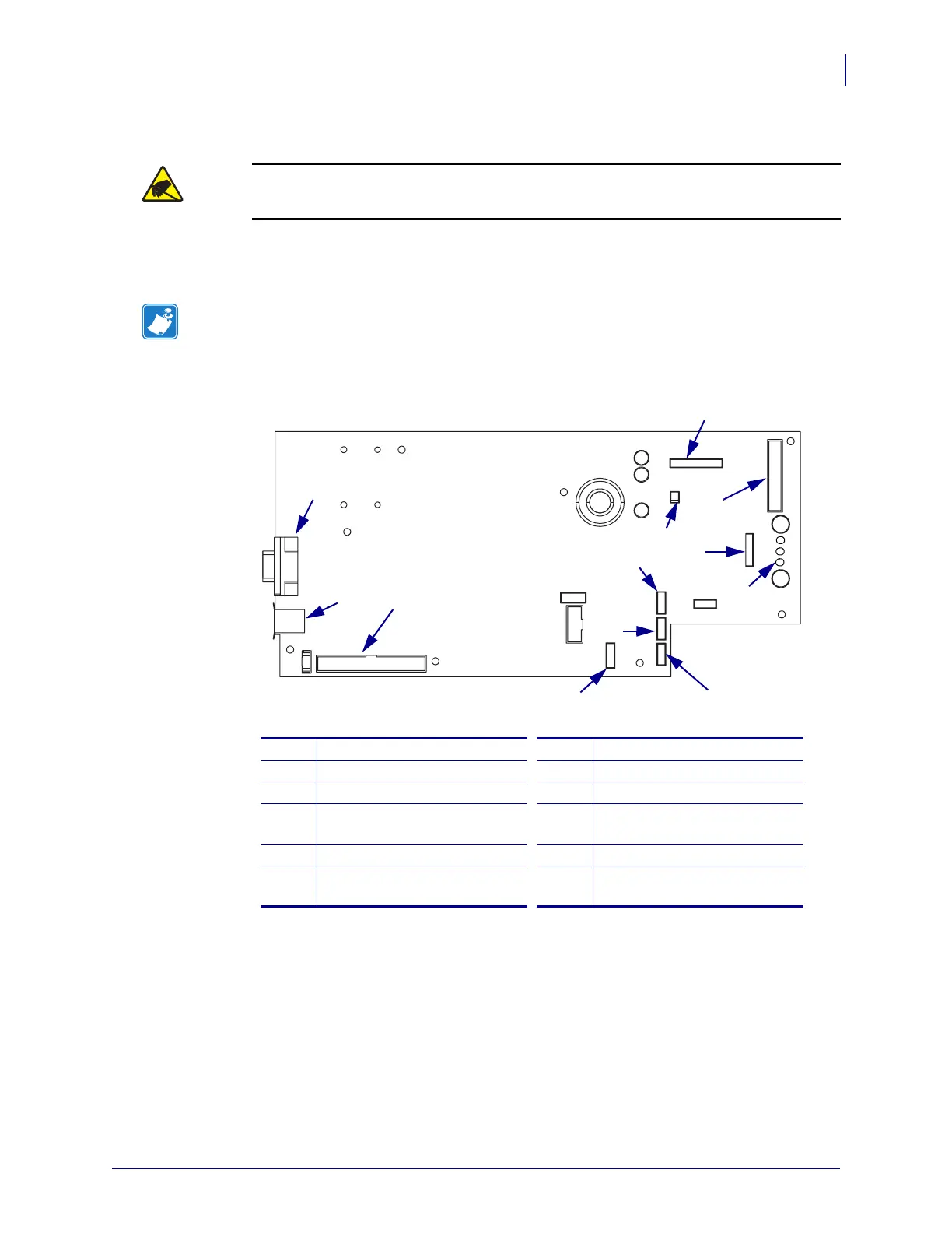
2. See Figure 4. Remove all cables from the main logic board (MLB).
Figure 4 • Remove the Main Logic Board Cables
3. See Figure 5. Remove the six screws and one nut securing the main logic board to the
frame of the printer.
4. Remove the two studs and washers securing the serial port connector to the back of the
printer.
Caution • Observe proper electrostatic safety precautions when handling
static-sensitive components such as circuit boards and printheads.
Note • Take note of the location of all cables on the main logic board.
1
Printhead Data (J3)
7
Transmissive Sensor (P9)
2
Power-in (J8)
8
Reflective Sensor (P7)
3
Front Panel (J2)
9
Take Label Sensor (J19)
4
Stepper Motor (J9)
10
Communication Expansion
Port (J17)
5
Booster Board (J7)
11
USB Port (J14)
6
Ribbon Sensor/Head Open
(P4)
12
Serial Port (J10)
F6
L
F
1A
1
2
3
4
5
6
7
8
10
11
12
9
 Loading...


