17
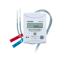
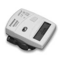
Installation ow sensor (FS)
■
Mount ball valves up- and down-
streamoftheowsensor.
■
Consider the correct installation
point. Normally this is the return
(thecolderpipeinheatingsys-
tems).Pleasenotethetypeplate
information.
■
Considerthecorrectowdirec-
tion. This is indicated by an arrow
onthesideoftheowsensor.
■
Theowsensorcanbeinstalled
inanyposition(also„overhead“).
■
Do not install at highest point of
pipingtoavoidairinsidetheow
sensor.
■
Consider the dimensions of the
heat meter.
Installation of the ball valve
■
Mount ball valves up- and down-
stream of the meter.
■
Mount a ball valve with bore
M10x1 for the temperature sensor
installation.
■
For symmetrical temperature sen-
sor installation, mount a second
identical ball valve.
Mounting heat/cooling energy meter
■
Flush the system thoroughly
before installing the heat/cooling
energy meter.
■
Close valves and release pressure.
■
Dismounttheexistingowsensor
/tting.
■
Useonlynewandawlesssealing
material, no hemp or similar!
Clean sealing surfaces and check
for damage.
■
Installthenewowsensorac-
cordingtothecorrectowdirec-
tion and installation position.
■
Turn heat computer to desired
reading position.
Installation of the temperature
sensors
■
The installation of the tempera-
ture sensors should be prefer-
ably symmetrical and as direct
installation.
■
Do not remove the temperatur
sensor if already mounted on
theowsensor.Thisisalsovalid
for all the safety seals which are
mounted on the device as a
standard.
■
Sensors are colour-coded
(accordingtothemodel):
Red = Pipe with higher tempera-
turelevel(supplyin„Heating“
modeandreturnin„Cooling“
mode)
Blue = Pipe with lower tempera-
turelevel(returnin„Heating“
modeandsupplyin„Cooling“
mode)
■
The connecting cables may not be
buckled, extended or shortened!
■
The seal at the sensor installation
pointontheowsensormaynot
be damaged.
■
Removelockingscrewandseal
at the ball valve completely, if
existing.
■
Attach the O-ring to the installa-
tionaid(the2ndO-ringisonlya
spareO-ring).Usingtheinstalla-
tion aid, insert the O-ring into the
installation point according to
DIN EN 1434 with a slight circular
motion.
■
Using the other end of the instal-
lation aid bring the O-ring into the
correct position.
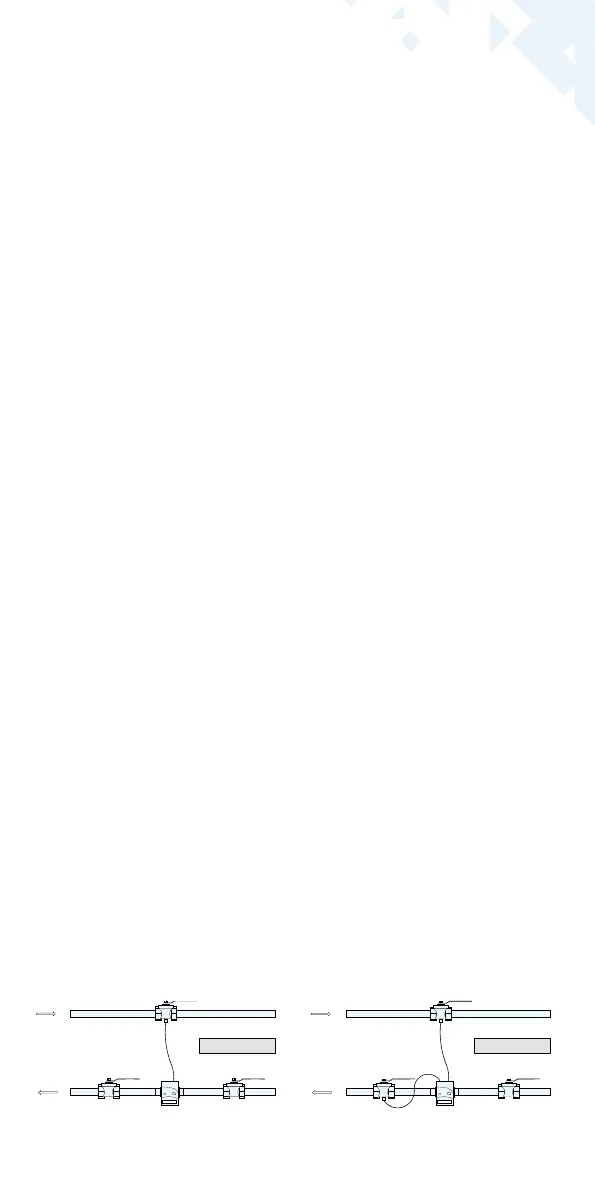
Asymmetrical sensor installation for
zelsius®C5-IUFwithonetemperaturesensor
integratedintheowsensor
Symmetrical sensor installation for
zelsius®C5-IUF
Supply
Return
Consumer
Supply
Return
Consumer
 Loading...