20
Programming of M-Bus address
(optional)
■
Selectofthedisplay„Adr000“in
level3(samefortheadditional
inputs„Adr1“to„Adr3“).
■
Press the button for about 2
seconds(untilthedoorsymbol
reappears)andthenrelease.The
rightdigitstartsashing.With
one short push the value of the
digit is incremented.
■
With each long press, the selected
value will be taken over and
changetonextdigit(assoonas
desiredcharacterashes,release
thebutton).
■
If the desired value is reached,
you have to press the button
untilthenumberstopsashing
and the return to the menu is
completed. Now the new value is
programmed.
■
The programming process can be
repeated if necessary.
Note: If the editor is not terminated,
maybe changed values are being
savedaertheautomaticreturnto
the main display.
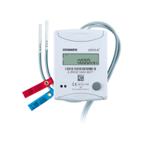
Radio (optional)
General information
zelsius®-energy meters which have
an integrated radio interface with an
antenna are marked for better visibil-
ity on the upper cover with one of the
following symbols:
wM-Bus
®
colour connection signication
white I/O 1 In-/Output 1
yellow I/O 2 In-/Output 2
green I/O 3 In-/Output 3
brown GND
common ground
for I/O 1-3
Technical data I/O
Load max. 30V DC/ 20 mA
I/O 1, 2, 3
Open Drain, n-channel
FET
Cable D=3.8mm,4-wire
Pulse-duty
factor
1:1(out);1:5(in)
Cable length 1.5m
Input fre-
quency
max. 1 Hz
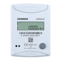
M-Bus (optional)
The optional M-Bus interface com-
plies with standard EN 1434-3 and
operateswith2400baudxed.The
two conductors can be connected in
any order to the M-Bus network.
Armlyattachedcableisincluded,
external wiring must be done by
oneself.
Technical data M-Bus
Cable length 1.5m
Cable D=3.8mm,2-wire
colour connection signication
brown M-Bus 1
M-Bus-
cable 1
white M-Bus 2
M-Bus-
cable 2
 Loading...