100
HYDRAULIC SYSTEM
P+11N019
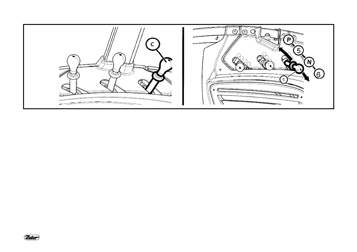
DIFFERENT FUNCTIONS OF OUTER HYDRAULIC CIRCUIT CONTROL LEVERS
There are four positions of the lever (b) which controls quick couplers (5) and (6):
N -
Neutral position. Quick coupler drives (5) and (6) are closed and oil in the hydraulic appliance connected is blocked. Lever
(c) is locked in this position.
5 -
Pressure in quick coupler (5). Quick coupler (6) is connected with the drain. It is necessary to hold lever (c) in this position,
when released, lever (c) automatically returns to (N) position. In addition, quick coupler (5) is equipped with a one-way
valve – convenient for connecting a tool which requires higher degree of impermeability – minimum lowering of the tool
during transport.
6 -
Pressure in quick coupler (6). Quick coupler (5) is connected with the drain. Lever (c) is locked in this position.
P -
Floating position. Both quick couplers (5) and (6) are connected with the drain and oil is free to flow in both directions.
Lever (c) is locked in this position.
 Loading...