184
ADJUSTMENT
C768 C769
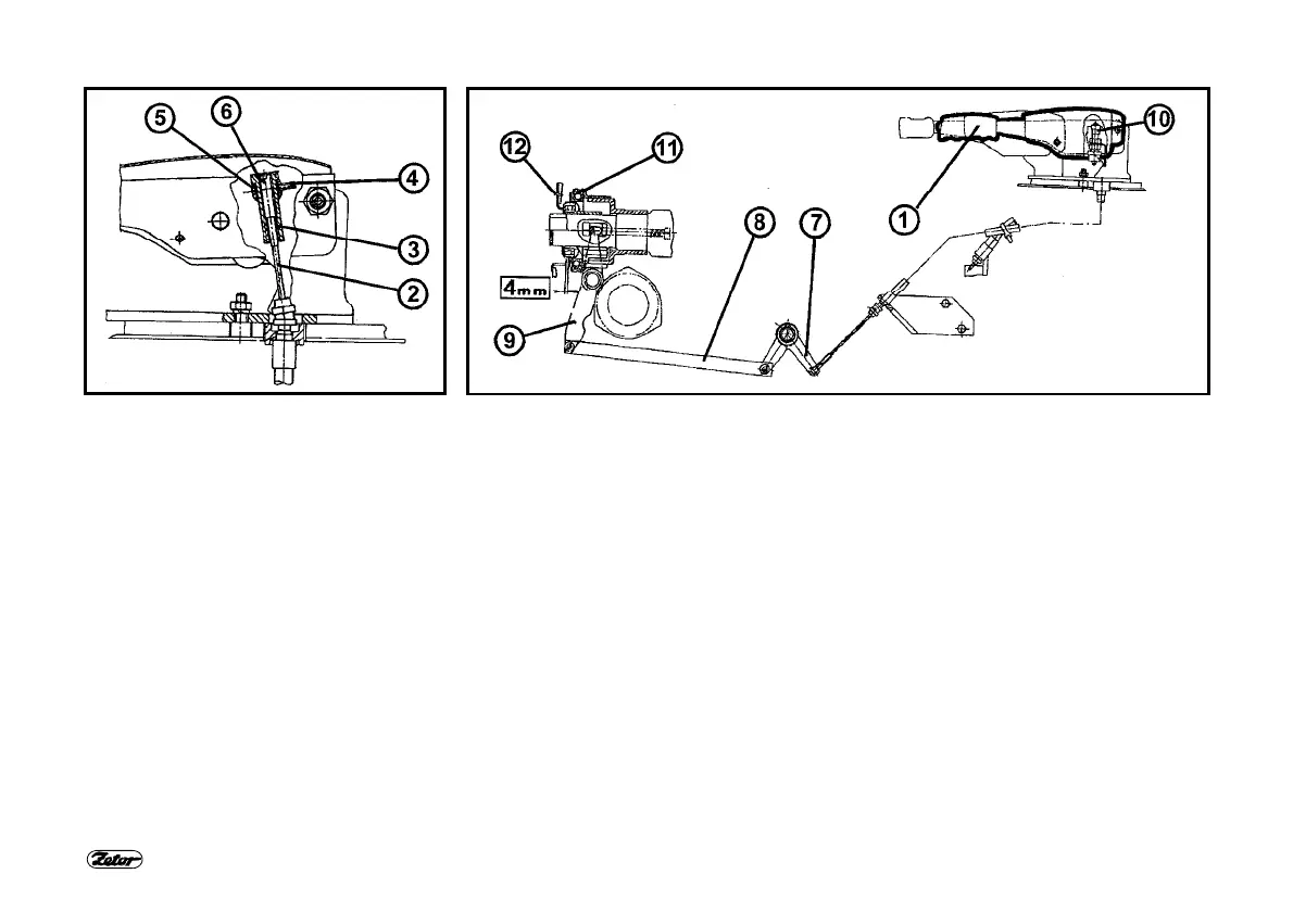
ADJUSTMENT OF MECHANICAL
CONTROL OF PTO CLUTCH
It works through the release bearing on
the PTO clutch levers.
1. Lever
2. Bowden cable
3. Adjusting nut
4. Adjusting screw
5. Pin
6. Bowden cable bolt
7. Two-arm lever
8. Draw rod
9. Shaft with lever
10. Electric switch
11. Bearing
12. Release levers of travel clutch
ADJUSTMENT PROCEDURE
1. Remove the plastic cover of the lever
of hand control of the PTO clutch.
2. Loosen the adjusting screw (4). This
way the adjusting nut (3) is released.
3. Adjust the play between the bearing
(11) and the clutch levers (12). Perform
the adjustment with the adjusting nut (3)
so that the play between the bearing (11)
and the clutch levers (12) might be 4
mm; at the same time it must not
decrease under 2,5 mm. During
adjusting hold the Bowden cable bolt (6)
in the adjusting nut (3) so that it could
not come to its turning together with the
adjusting nut (3) and so to plying apart of
the Bowden cable (2).
4. After adjusting secure the adjusting nut
(3) with the adjusting screw (4). Check,
that seating surface of the adjusting nut
(3) is seated at upper surface of the pin
(5).
5. By shifting of the lever (1) to the
disengaged position, the indicator lamp
at the dashboard must be “on”.
6. When the release levers of the travel
clutch are adjusted properly, the control
force at the lever (1) is max. 200 N. If the
force increases non-proportionally (ca 2
times) it is necessary to adjust the
release levers of the travel clutch.
 Loading...