INSTALLATION
12 • Residenal Hybrid Electric Heat Pump Water Heater Use and Care Guide
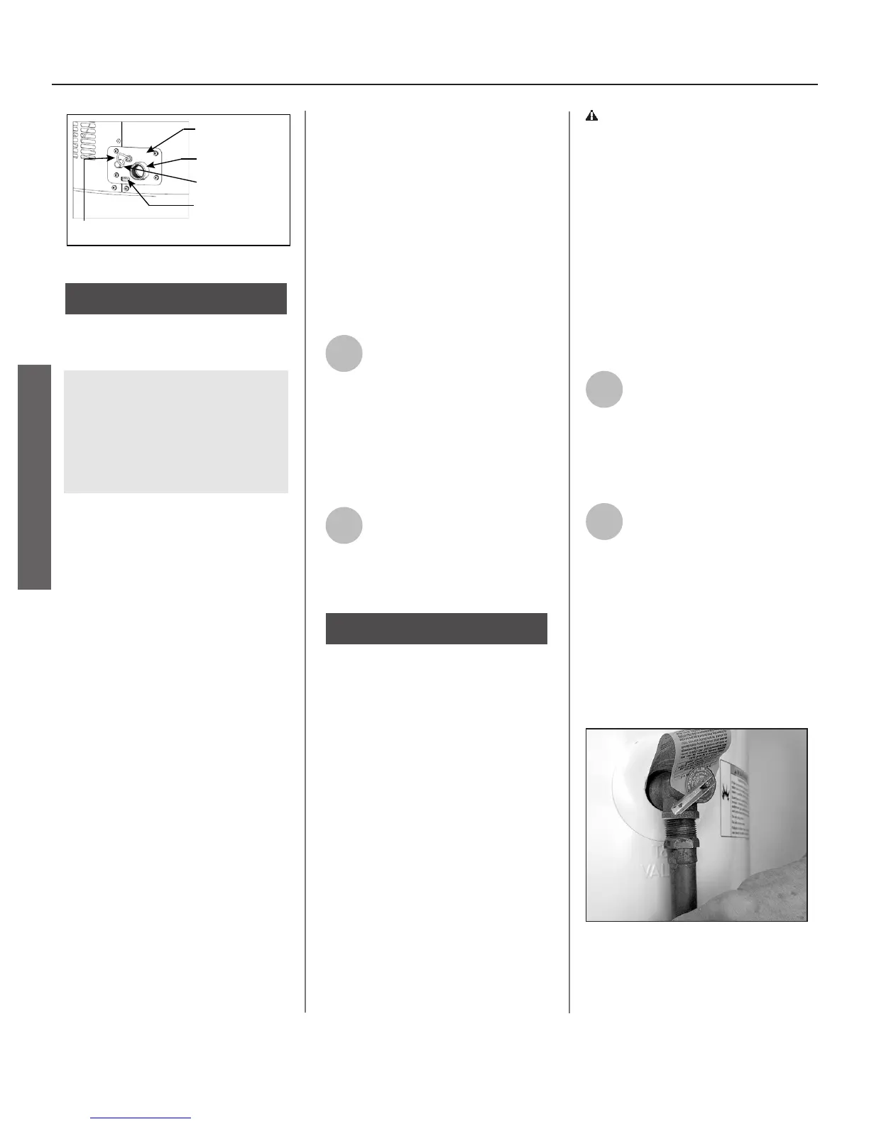
Overflow Slot
Primary Drain
Connection
Condensate Drain
Access Cover
Condensate Pump Wiring
(Loop Located Close to the Drain Connections)
Secondary Drain
Connection
Figure 14 - Condensate Pump Wiring
When making condensaon
connecons to the primary connec-
on DO NOT overghten! These con-
necons should be HAND TIGHTENED
ONLY. Overghtening could crack or
damage the condensate drain pan.
• Plasc pipe or tubing must be
used to connect the condensate
drain to a suitable drain or con-
densate pump.
• Condensate drain lines should
be installed in condioned areas
only.
• Do not connect condensate
drain lines with other drain or
discharge lines into a single (com-
mon) pipe or line. Each line (con-
densate drain line, temperature
and relief valve discharge pipe,
etc.) should be independently
run to an adequate drain.
• Slope the condensate drain lines
toward the inside oor drain or
condensate pump.
• The condensate drain lines and
connecons to the drain piping
must comply with all local codes.
• Use appropriate ngs and
primer to cement the condensate
drains to the heat pump drain
pan.
• If a condensate pump is installed,
it should be wired to shut o the
heat pump in the event the con-
densate pump fails or the oat
switch in the pump acvates (see
step 5 on page 11).
1
Using 3/4” PVC piping, a 90°
elbow that is 3/4” slip & 3/4”
NPT and an approved sealant
(none supplied with unit), aach the
elbow to the primary drain connec-
on and insert the PVC pipe into the
female end allowing enough length to
access an adequate drain.
2
Using 1/2” ID rubber or exi-
ble plasc tubing, slip one
end over the secondary drain
connecon allowing enough length to
access an adequate drain.
-
Most T&P Relief Valves are pre-
installed at the factory. In some cases,
they are shipped in the carton and
must be installed in the opening
marked and provided for this purpose
and according to local codes. .
WARNING!
If your water heater does not have
a factory installed T&P Relief Valve,
install the new T&P Relief Valve that
came with your water heater. Do not
reuse an old T&P Relief Valve. Install
a T&P Relief Valve discharge pipe
according to local codes and the fol-
lowing guidelines:
1
The discharge pipe should be
at least 3/4” inside diameter
and sloped for proper
drainage. Install it to allow complete
drainage of both the T&P Relief Valve
and the discharge pipe.
2
The discharge pipe must
withstand 250°F (121°C)
without distoron. Use only
copper or CPVC pipe. Most homes
use copper water pipes or cross-linked
polyethylene (PEX), but some use
CPVC. Use ngs appropriate for the
type of pipe in your home. Do not use
any other type of pipe, such as PVC,
iron, exible plasc pipe, or any type
of hose.
Figure 15 - The T&P Relief Valve discharge
pipe must be installed properly and piped
to an adequate drain.
INSTALLATION
 Loading...