Electrical connections
30 265Gx, 265Ax IM/265Gx/Ax-EN-07
Delivery scope
HART devices Gland/mating plug
M20 x 1.5 cable entry Plastic cable gland
(6 … 12 mm clamping area)
1/2 - 14 NPT Not included in delivery scope
Han 8D (8U) device plug Socket connector
Bus devices (PA/FF) Gland/mating plug
M20 x 1.5 cable entry Metal cable gland
(6 … 12 mm clamping area)
1/2 - 14 NPT Not included in delivery scope
M12 x 1 connector Not included in delivery scope
7/8" connector Not included in delivery scope
Terminal assignment
Terminals Description
Signal (+) and (-) Operating voltage
Test (+) and (-) Test terminals for 4 ... 20 mA (HART); not
available with fieldbus transmitters
2
3
4
~
~
+
-
M00038
1
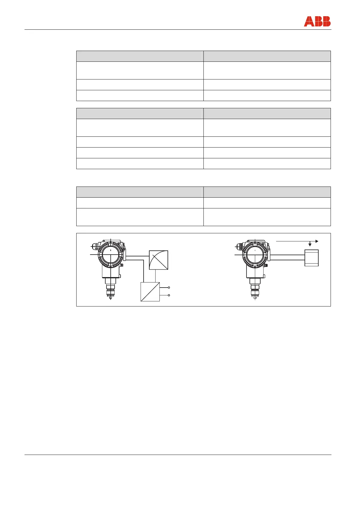
Fig. 8: Connection diagram, left: 4 … 20 mA current output with HART communication protocol
and supply power; right: PROFIBUS PA or FOUNDATION Fieldbus
1 E.g., ammeter in 4 ... 20 mA circuit
2 Supply power / Power supply unit:
Non-Ex applications: 10.5 (14) ... 45 V
Ex applications
1)
: 10.5 (14) ... max. 30 V
(intrinsically safe)
3 PROFIBUS PA or
FOUNDATION Fieldbus
4 PROFIBUS PA:
Connection to PLC or PC via segment
coupler
FOUNDATION Fieldbus:
Connection to PLC or PC via FF supply
unit
1)
Important: If, when using transmitters with type of protection "intrinsic safety", an ammeter is connected to the
output circuit or a modem is connected in parallel while there is a risk of explosion, the sums of the capacitances
and inductances of all circuits, including the transmitter (see EC-type-examination certificate) must be equal to or
less than the permissible capacitances and inductances of the intrinsically safe signal circuit (see EC-type-
examination certificate for the supply unit). Only passive or explosion-proof devices or indicators may be connected.
 Loading...


