Electrical connections
IM/265Gx/Ax-EN-07 265Gx, 265Ax 29
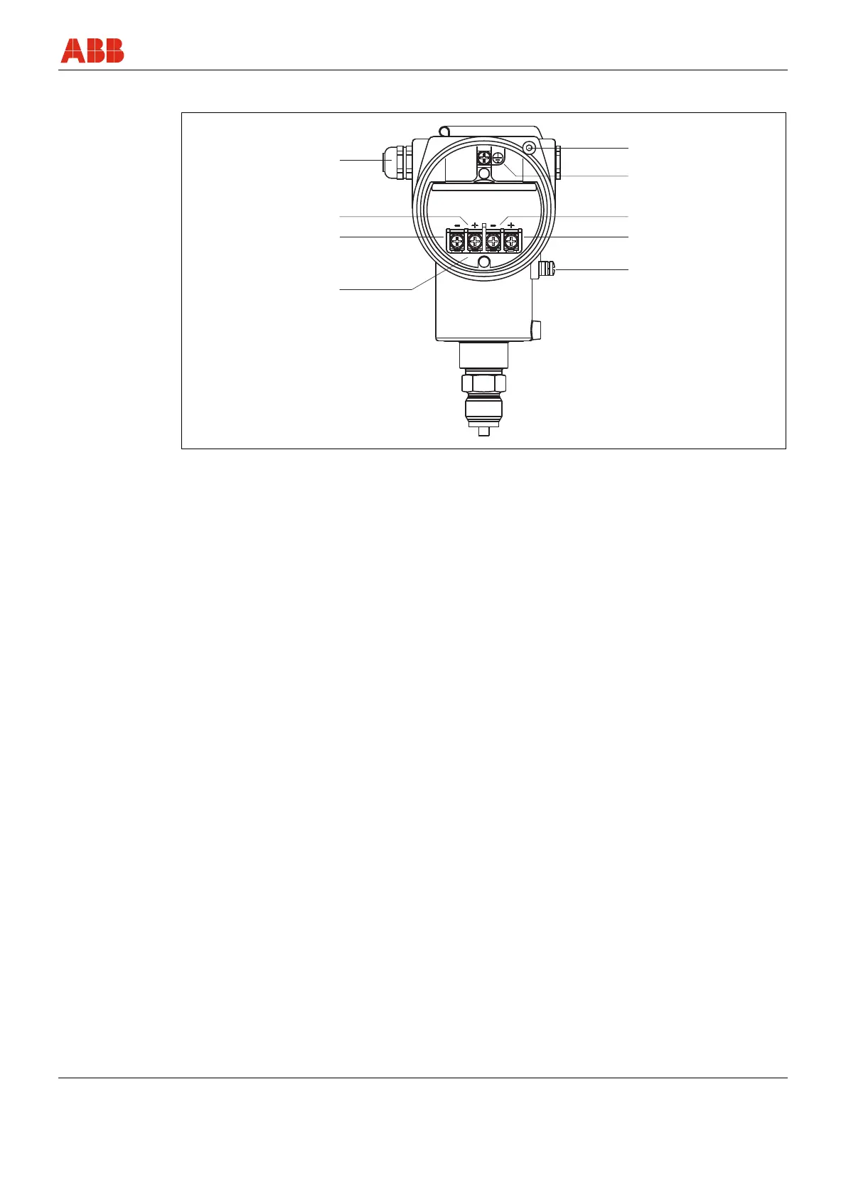
5.2 Electrical connection in the cable connection area
2
3
4
5
6
7
8
9
M00037
1
Test
Signal
Fig. 7: Cable connection area
1 Screw terminals for 0.5 … 2.5 mm
2
-
(AWG 20 ... AWG 14) wire
2 Test terminals for 4 ... 20 mA (not with
Fieldbus transmitters)
3 Test
4 Cable entry (e.g., via M20 x 1.5)
5 Ex d locking screw
6 Grounding/equipotential bonding terminal
7 Signal
8 Output signal/operating voltage
9 Grounding/equipotential bonding terminal
The electrical connection is established in the connection area. The housing cover must be
unscrewed for this purpose.
The M20 x 1.5 cable glands, which are supplied by the manufacturer, are screwed only loosely
into the electronics housing. In order to achieve protection type IP 67, the glands must be
screwed in using a suitable tool (hexagon head, SW 22) until they are hand-tight.
 Loading...


