Specifications
70 265Gx, 265Ax IM/265Gx/Ax-EN-07
9 Specifications
9.1 Functional specifications
Change from one to two colu mns
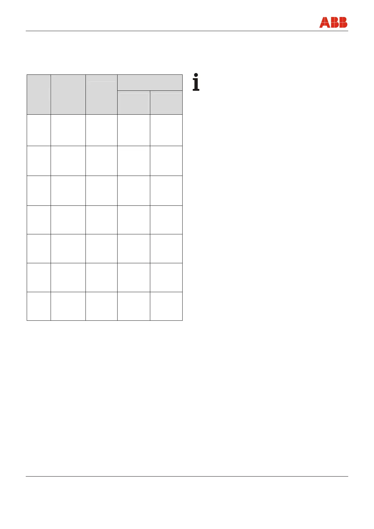
Measuring range and span limits
Minimum measuring
span
Sensor
code
Upper range
limit (URL)
Lower
range limit
(LRL)
for 265G
265G
Gauge
pressure
265A
Absolute
pressure
C
6 kPa
60 mbar
24 in H
2
O
-6 kPa
-60 mbar
-24 in H
2
O
0.2 kPa
2 mbar
0.8 in H
2
O
0.3 kPa
3 mbar
2.25 mm Hg
F
40 kPa
400 mbar
160 in H
2
O
-40 kPa
-400 mbar
-160 in H
2
O
0.4 kPa
4 mbar
1.6 in H
2
O
2 kPa
20 mbar
15 mm Hg
L
250 kPa
2,500 mbar
1,000 in H
2
O
Absolute 0
2.5 kPa
25 mbar
10 in H
2
O
12.5 kPa
125 mbar
93.8 mm Hg
D
1,000 kPa
10 bar
145 psi
Absolute 0
10 kPa
0.1 bar
1.45 psi
50 kPa
0.5 bar
7.25 psi
U
3,000 kPa
30 bar
435 psi
Absolute 0
30 kPa
0.3 bar
4.35 psi
150 kPa
1.5 bar
21.7 psi
R
10,000 kPa
100 bar
1,450 psi
Absolute 0
100 kPa
1 bar
14.5 psi
500 kPa
5 bar
72.6 psi
V
60,000 kPa
600 bar
8,700 psi
Absolute 0
600 kPa
6 bar
87 psi
IMPORTANT (NOTE)
The lower range limit (LRL) for 265A is 0 absolute for all
measuring ranges.
Span limits
Maximum span = URL = Upper range limit
To optimize performance characteristics, it is recommended that you
select the transmitter sensor with the lowest turndown ratio.
TURNDOWN = Upper range limit/set span
Zero position suppression and elevation
The zero position and span can be set to any value within the range
limits listed in the table if:
- Set span ≥ minimum span
Damping
Adjustable time constant: 0 … 60 s
This is in addition to the sensor response time, and can be set via the
optional LCD display, handheld terminal, or PC user interface.
Operational readiness
According to technical data, ready for operation in ≤ 2.5 s after
switching on the transmitter, with minimum damping.
Insulation resistance
>100 MΩ at 500 V DC (between terminals and ground)
Change from one to two colu mns