Chapter 3 – Electrical Installation
3-20 ACA 6xx Sections and ACS/ACC 6x7 (132 to 3000 kW) Frequency Converters
Inverter Modules R8i
and Above
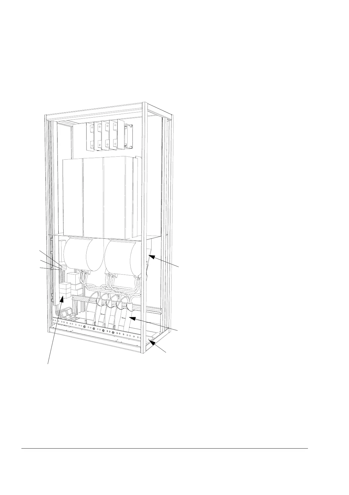
The cable connections of a bottom entry unit are represented below.
For top exit, an extra cabinet is required (200 mm to 800 mm, see next
page).
Motor cable connection
1. Disconnect the fan power lead.
2. Remove the fan.
3. Strip the cable 3 cm at the cabinet entry
if EMC sleeves are used.
4. Lead the cable unstripped to the busbar
terminals behind the fan.
5. Connect the cables to the terminals with
cable lugs.
6. Connect the shield conductor to the
PE busbar.
7. Replace the fan.
8. Connect the fan power lead.
Control cable connection:
Connect the control cables to the appropriate
terminal block on the DIN rail. (ACx 6x7 units 630
to 3000 kW: the DIN rail is located in the Auxiliary
Control Unit (ACU).)
PE terminal of
the cabinet
Motor cables
Busbars for motor
cable connection:
U2, V2, W2.
F10
F31
(F11, F12)

 Loading...


