Chapter 4 – Control Operation
ACH 500 Programming Manual 4-7
Keypad Control vs.
External Control
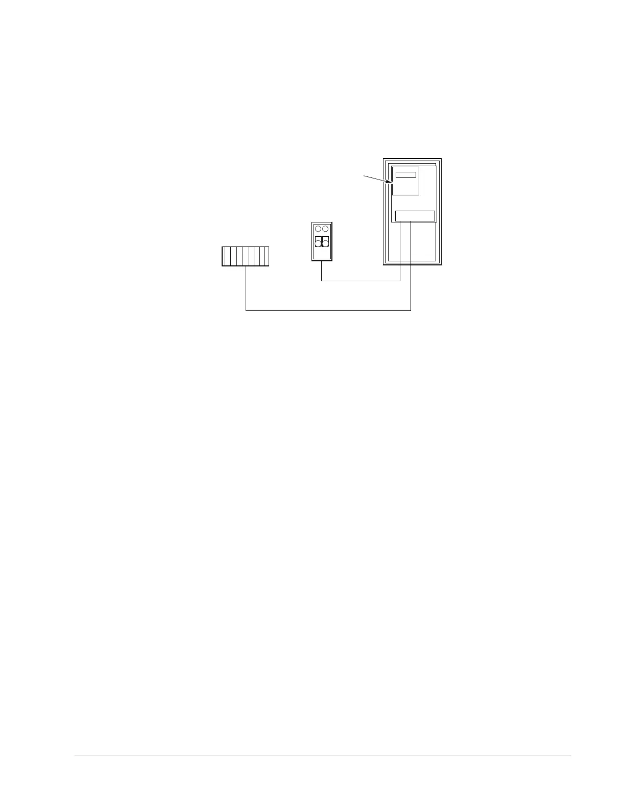
The ACH 500 can be controlled from two external control locations, of which
one is the cover-mounted HOA switch and speed pot or from the Control
Panel keypad. Figure 4-2 shows all control locations.
Figure 4-2 Control Locations
Select Operating Data Parameter 9 (Control Location), then select KEYPAD
R1 for keypad control or EXTERNAL for external control or control via cover-
mounted devices. The valid control location is indicated on the display.
Square brackets around the Direction and Run indicators on the LCD Display
mean Keypad control. No square brackets means External control. R1 on the
LCD means Ref 1 and R2 means Ref 2.
Keypad Control
When you select KEYPAD R1 or KEYPAD PI from Operating Data
Parameter 9, Keypad commands operate the ACH 500.
External Control
External control locations Ref 1 and Ref 2 are selected with digital inputs
1 – 6 or Operating Data Parameter 12 (Ext Ref 1 or 2), depending on the
setting of Parameter 11.2 (Ext 1/Ext 2 Select). The factory setting is D16, so
the HOA switch makes the selection.
Figure 4-3 shows a signal flow diagram indicating the control signal
selections.
Keypad Control
(R1 or PI)
External Control
(cover-mounted HOA
External Control
such as a PLC
(automatic).
R1
R2
switch and speed pot)
 Loading...


