Chapter 5 – Standard Application Macro Programs
ACH 500 Programming Manual 5-9
Application 3 –
HVAC-PI
Start/Stop from two different places, Control Location selection, Run Enable
selection, one Preset Speed selection, Reference setting and actual value
feedback through screw terminal inputs. Reference setting also possible
internally with the keypad.
Place A is intended for direct speed setting with a reference signal and Place
B is intended for closed-loop speed control using the same reference as Place
A. Preset speed overrides external analog settings.
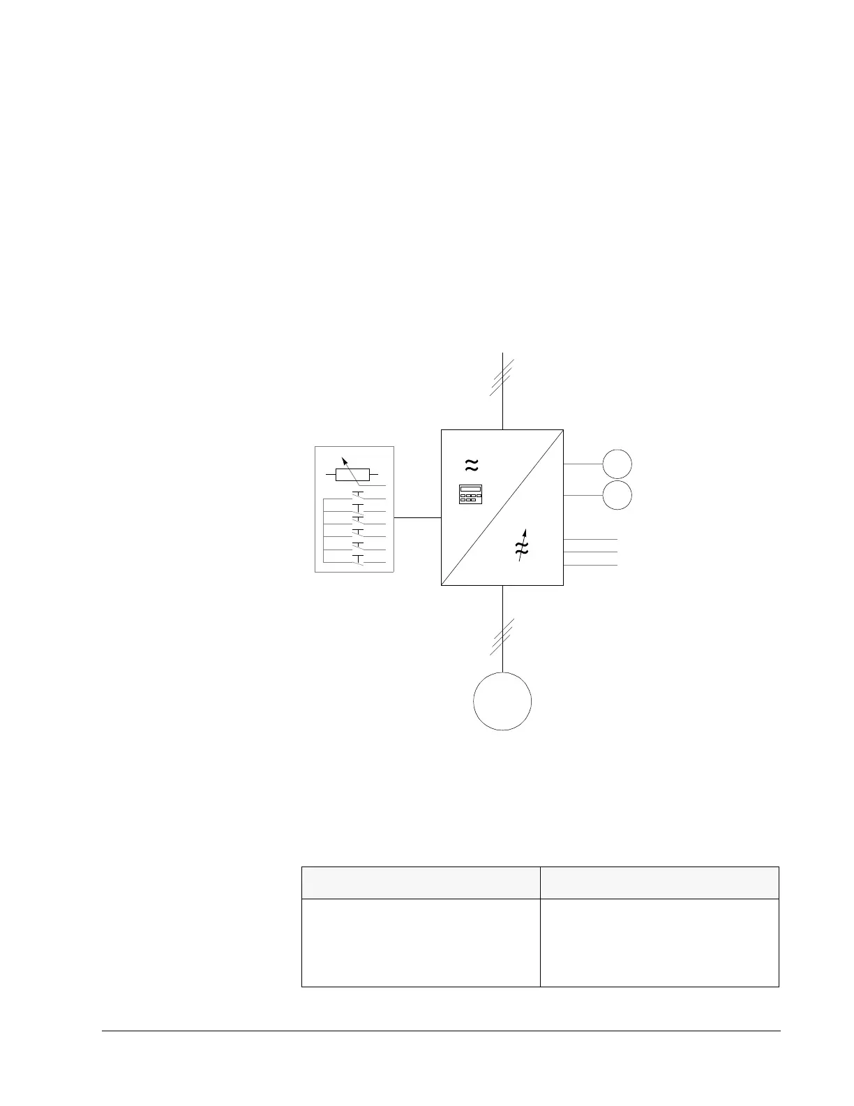
Operation Diagram
Figure 5-5 Operation Diagram
Input and Output
Signals
Table 5-4 Input and Output Signals
Input Signals Output Signals
Two Analog Reference inputs.
Six Digital Inputs: Start Hand, Start Auto,
Preset Speed (2), Auto Select, and Run
Enable.
Analog Output AO1: Output Frequency
Analog Output AO2: Output Current
Relay Output RO1: READY
Relay Output RO2: RUN
Relay Output RO3: FAULT
f
A
M
3Φ
Output
Current
Relay
Outputs
Motor
Ext. Controls
Input
Power
location
 Loading...


