ACH580 Installation, Operation and Maintenance Manual 29
ACH580-01 Installation
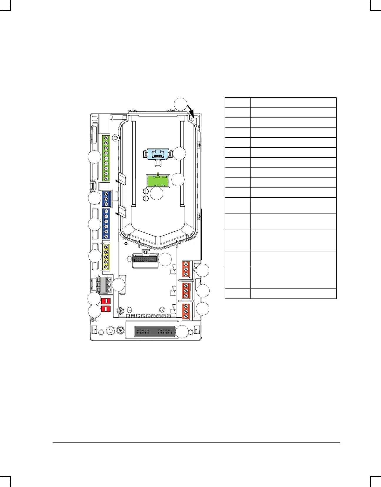
External control connection terminals, frames R1…R5
The layout of the external control connection terminals of the R1 frame is shown
below. Layout of the external control connection terminals is identical in frames
R1…R5 but the location of the control board with the terminals is different in frames
R3…R5.
Description
X1 Analog inputs and outputs
X2 Aux. voltage output
X3 Programmable digital inputs
X4 Safe torque off connection
X5 Embedded fieldbus
X6 Relay output 3
X7 Relay output 2
X8 Relay output 1
X10 Auxiliary fan connection (IP55)
X13
Option slot 1 (fieldbus adapter
modules)
X14
Option slot 2 (I/O extension
modules)
S4, S5
Termination switch (S4), bias
resistor switch (S5), see
section Switches on page 43
1
Panel port (control panel
connection)
2
Cold configuration connection. This
connector is used with the CCA-01
configuration adapter.
3 Power OK and Fault LEDs
1
2
3
S4
X5
S5
X13
X14
X3
X2
X4
X1
X6
X7
X8
X10
R1…R5
ACH580_Inst_Op_Maint_Rev G.book Page 29

 Loading...