 Loading...
Do you have a question about the ABB ACH580-01 and is the answer not in the manual?
| Input Frequency | 50/60 Hz |
|---|---|
| Enclosure Type | IP21, IP55 |
| Input Voltage | 380 to 480 V |
| Output Voltage | 0 to Input Voltage |
| Control Method | Vector control |
| Communication Protocols | Modbus RTU, BACnet |
| Cooling Method | Air Cooling |
| Mounting | Wall Mounting, Floor Mounting |
| Protection Features | Overload, Short-circuit, Overvoltage, Undervoltage |
Explains the meaning of warning symbols used in the manual.
Provides general safety guidelines for personnel performing installation and maintenance.
Details electrical safety precautions for installation and maintenance tasks.
Lists essential steps to take before commencing any electrical work on the drive.
Specifies the minimum free space needed around the drive for proper ventilation and access.
Steps to prepare the installation site and handle the drive before mounting.
Lists the necessary tools for installing the ACH580 drive.
Detailed instructions for vertically mounting drives in frames R1 through R4.
Instructions on how to check the insulation resistance of the drive assembly.
Guidelines for making proper ground connections for safety and EMC.
Methods for identifying electrical power system types for configuration.
Explains the purpose and configuration of EMC filters and varistors.
Electrical ratings for the drive at 208 V supply voltage according to UL standards.
Electrical ratings for the drive at 460 V supply voltage according to UL standards.
Electrical ratings for the drive at 575 V supply voltage according to UL standards.
Specifies fuse types and ratings for 208-240 V operation.
Specifies fuse types and ratings for 380-480 V operation.
Specifies fuse types and ratings for 500-600 V operation.
Diagram and description of external control terminals for frames R1 to R5.
Diagram and description of external control terminals for frames R6 to R9.
Instructions for conduit wiring for drives in frames R1 and R2.
Torque specifications for power wiring connections for frames R1 and R2.
Instructions for conduit wiring for drives in frame R3.
Default I/O connections for HVAC applications.
Default connections for PID control of a single motor.
How to wire digital inputs using PNP or NPN configurations.
Checklist of essential checks before applying power to the installed drive.
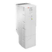
Steps for reinstalling covers on various drive frames.
Instructions for installing the protective hood on IP55 drives.
Information required from the motor nameplate for drive setup.
Overview of the drive's default control configurations.
Description of the ACH580 control panel buttons and their functions.
Explanation of the elements shown on the ACH580 control panel display.
Guides users through initial setup, including language and basic motor data.
How to select localization and configure display units for the control panel.
Entering motor data and performing a direction test for correct motor rotation.
Steps for completing commissioning for HVAC or PID control setups.
Navigating primary settings for commissioning the drive.
How to adjust and verify I/O settings within the Primary settings menu.
Explains causes and actions for overcurrent and earth leakage warnings.
Details warnings related to short circuits, IGBTs, and DC link voltage issues.
Explains warnings related to drive temperature, cooling fans, and IGBTs.
Explains faults related to backup/restore operations and rating ID reading.
Details faults concerning short circuits, IGBT overload, and DC link voltage issues.
Explains faults related to drive temperature, cooling fans, and IGBTs.
Recommended maintenance intervals and component replacement schedule.
Step-by-step guide for cleaning the drive's heatsink.
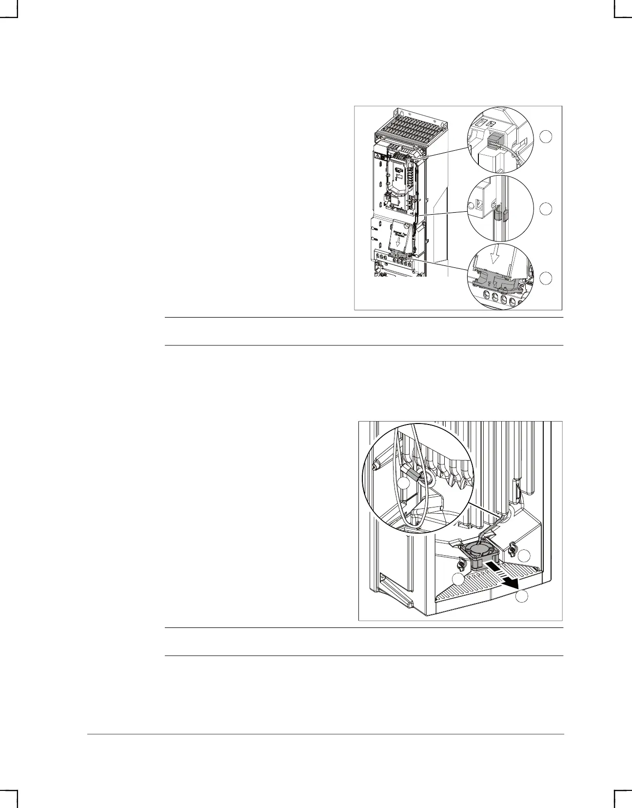
Instructions for replacing main cooling fans in drive frames R1 through R8.
Guidelines for reforming capacitors if the drive has been unpowered for an extended period.
Procedures for cleaning the control panel and replacing its battery.