22
5.5. Drive and Motor Connection
The drive inherently produces fast switching of the output voltage (PWM) to the motor compared to the mains supply, for motors
which have been wound for operation with a variable speed drive then there is no preventative measures required, however if the
quality of insulation is unknown then the motor manufacturer should be consulted and preventative measures may be required.
The motor should be connected to the ACS255 U, V, and W terminals using a suitable 3 or 4 core cable. Where a 3 core cable is utilised,
with the shield operating as an earth conductor, the shield must have a cross sectional area at least equal to the phase conductors
when they are made from the same material. Where a 4 core cable is utilised, the earth conductor must be of at least equal cross
sectional area and manufactured from the same material as the phase conductors.
The motor earth must be connected to one of the ACS255 earth terminals.
For compliance with the European EMC directive, a suitable screened (shielded) cable should be used. Braided or twisted type
screened cable where the screen covers at least 85% of the cable surface area, designed with low impedance to HF signals are
recommended as a minimum. Installation within a suitable steel or copper tube is generally also acceptable.
The cable screen should be terminated at the motor end using an EMC type gland allowing connection to the motor body through the
largest possible surface area
Where drives are mounted in a steel control panel enclosure, the cable screen may be terminated directly to the control panel using a
suitable EMC clamp or gland, as close to the drive as possible.
For IP66 drives, connect the motor cable screen to the internal ground clamp
5.6. Motor Terminal Box Connections
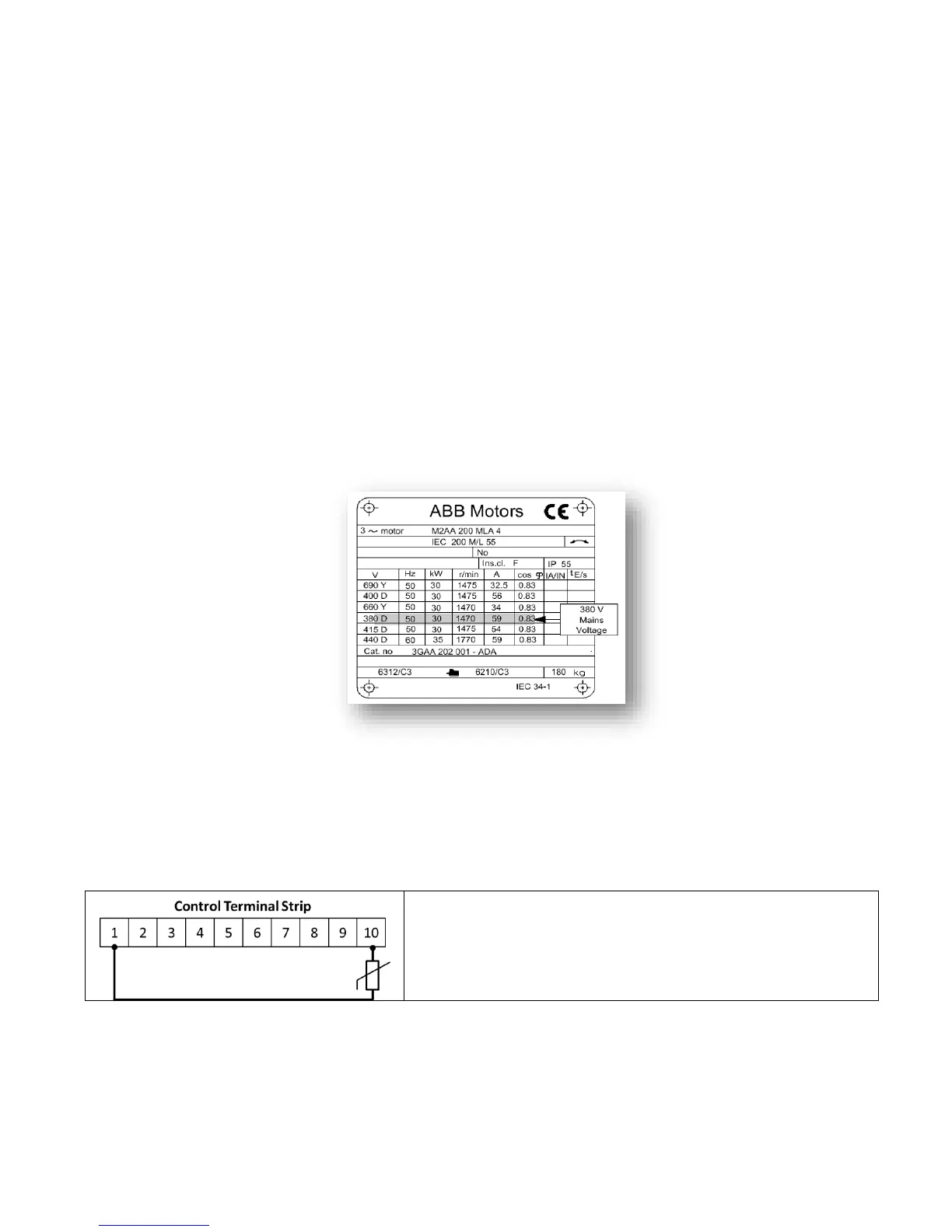
Most general purpose motors are wound for operation on dual voltage supplies. This is indicated on the nameplate of the motor
This operational voltage is normally selected when installing the motor by selecting either STAR or DELTA connection. STAR always gives the
higher of the two voltage ratings. . Example Motor nameplate shown below (380V Delta illustrated):
5.7. Motor Thermal overload Protection.
5.7.1. Internal Thermal overload protection.
The drive has an in-built motor thermal overload function; this is in the form of an “F0009” trip after delivering >100% of the value set in
parameter 9906 MOTOR RATED CURRENT for a sustained period of time (e.g. 150% for 60 seconds).
5.7.2. Motor Thermistor Connection
Where a motor thermistor is to be used, it should be connected as follows :-
5.8. Control Terminal Wiring
All analog signal cables should be suitably shielded. Twisted pair cables are recommended.
Power and Control Signal cables should be routed separately where possible, and must not be routed parallel to each other.
Signal levels of different voltages e.g. 24 Volt DC and 600 Volt AC, should not be routed in the same cable.
Maximum control terminal tightening torque is 0.5Nm.
Control Cable entry conductor size: 0.05 – 2.5mm
2
/ 30 – 12 AWG.