23
5.9. Connection Diagram
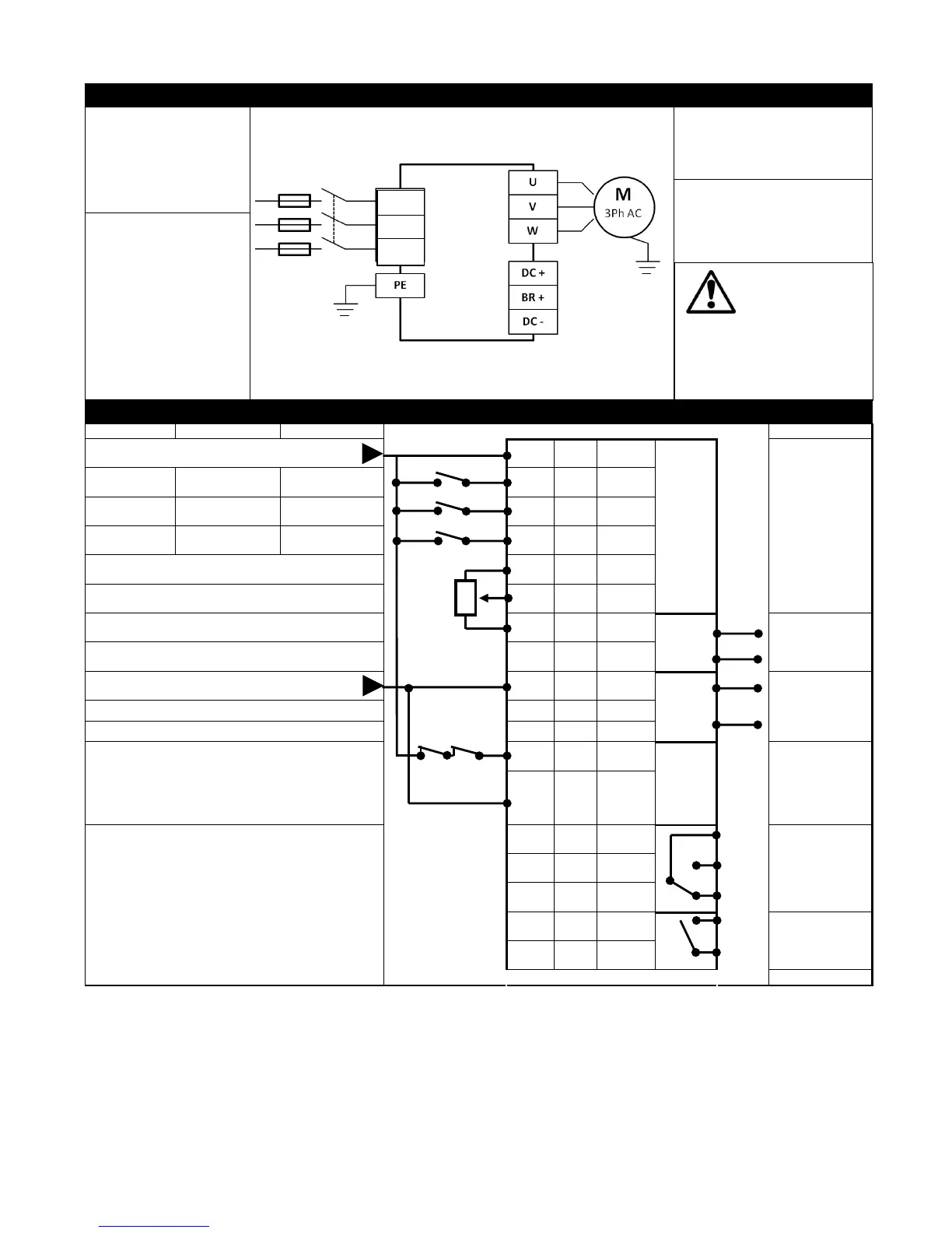
5.9.1. Power Terminal Designations
Incoming Power Source
Connect to L1, L2 & L3
terminals.
Phase sequence is not
important.
Motor Connections
Connect the motor to the U, V & W
terminals.
The motor earth must be connected
to the drive
Optional Brake Resistor & DC Bus
Connections
Where a Brake resistor is used, it
must be connected to the “BR” and
“+” terminals.
Protective Earth / Ground
connection.
The drive must be Earthed /
Grounded
5.9.2. Control Terminal Connections & Factory Settings
+24V Supply (100mA) / External Input
Digital Inputs : 8 – 30 Volt DC
+ 10 Volt, 10mA Output
Analog Output : 0 – 10 Volt / 4-20mA, 20mA Max
0 Volt Supply / External Input
Analog Output : 0 – 10 Volt / 4-20mA, 20mA Max
SAFE TORQUE OFF Input
Also refer to page 24 for further information on the STO
Function.
Logic High = 18-30 Volt DC (“SAFE TORQUE OFF” Standby
mode)
Relay Contacts (Terminals 14-18)
250VAC / 30VDC
5A Maximum
Default Function :
Drive Ready
/ Fault
Default Function :
Running
The brake resistor
should be protected from
overheating by means of a
thermal switch which interrupts
the mains supply in a brake
resistor fault situation.

 Loading...


