Resistor braking
125
ACS800-07/U7
If ordered, the resistors are factory installed in a cubicle(s) next to the drive cabinet.
Protection of frame sizes R2 to R5 (ACS800-01/U1)
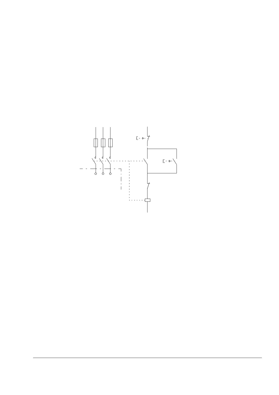
It is highly recommended to equip the drive with a main contactor for safety reasons.
Wire the contactor so that it opens in case the resistor overheats. This is essential
for safety since the drive will not otherwise be able to interrupt the main supply if the
chopper remains conductive in a fault situation.
Below is a simple example wiring diagram.
Protection of frame size R6 (ACS800-01, ACS800-07) and frame sizes R7
and R8 (ACS800-02, ACS800-04, ACS800-07)
A main contactor is not required for protecting against resistor overheating when the
resistor is dimensioned according to the instructions and the internal brake chopper
is in use. The drive will disable power flow through the input bridge if the chopper
remains conductive in a fault situation. Note: If an external brake chopper (outside
the drive module) is used, a main contactor is always required.
A thermal switch (standard in ABB resistors) is required for safety reasons. The
cable must be shielded and not longer than the resistor cable.
ACS800
U1 V1 W1
L1 L2 L3
1
2
3
4
5
6
13
14
3
4
1
2
K1
Q
Fuses
OFF
ON
Thermal switch (standard
in ABB resistors)

 Loading...