A1-A2 Power supply
T1-T2 Measuring circuit with 1…3 sensors.
S1-T2 Remote reset push button switch
WARNING! Even though autoreset of the relay can be
implemented by connecting these terminals together, this
is not recommended when used in the protection function
of an Ex motor.
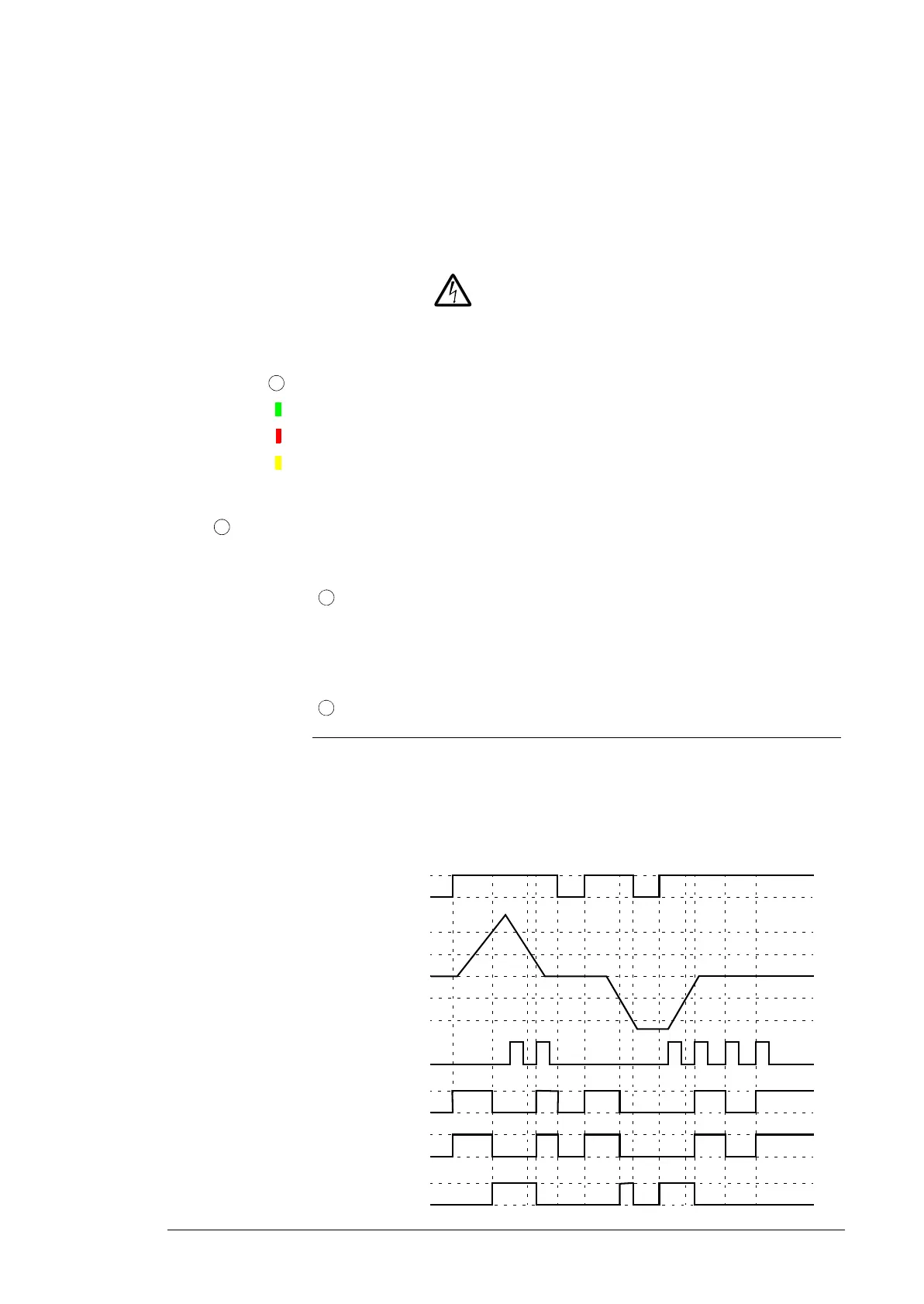
11-12/14 Output contacts (1)
•11: Common
• 12: Normally-closed
• 14: Normally-open
21-22/24 Output contacts (2)
• 21: Common
• 22: Normally-closed
• 24: Normally-open
Test / Reset Fault reset button
Reset = Confirms a rectified fault, a reset device after test routine,
or a change in configuration. Only possible if measured value is
less than the switch-on resistance.
LEDs Indication of operational states
“U” LED (green) Supply voltage present
“F” LED (red) Fault message (excessive motor temperature, or wire breakage or
short-circuit in the measurement circuit)
“R” LED (yellow) Output relay status
DIP switches
Position 1 2 3 4
ON Not in
use
Not in
use
Short-circuit detection
de-activated
Non-volatile fault
storage de-activated
OFF
(default)
Not in
use
Not in
use
Short-circuit detection
activated
Non-volatile fault
storage activated

 Loading...


