24 ATEX-certified motor thermal protection function with PTC thermistor relays (+L513+Q971)
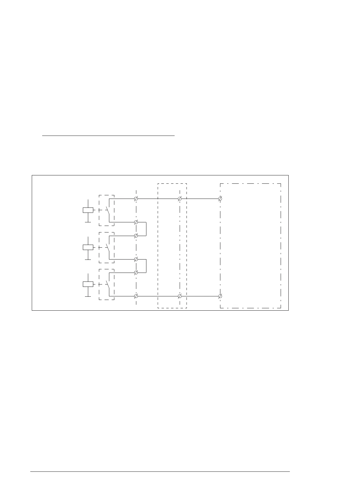
Wiring example
In this example, contacts of the PTC thermistor relay(s) are wired to digital input DI6 of the
drive control unit for indication purposes.
1. Connect the PTC sensor(s) of the motor to the PTC thermistor relay(s) [K74] (and
[K75] and [K76] if present) through terminal block [X506].
2. Connect a +24 V DC source via contacts 11 and 14 of the PTC thermistor relay(s)
(pre-wired to terminal block [X506] at the factory) to digital input DI6 on the drive
control unit. The contacts are wired in series.
3. Connect a reset button for the PTC relay(s) via terminal block [X506] (recommended).
4. With an FSO module (not shown in the figure)
:
• If necessary, connect a reset circuit to an input of the FSO module (for example,
DI X113:2).
See the circuit diagrams delivered with the drive for the actual wiring and terminals. For a
wiring diagram example, see page 73.
Drive control unit
(ZCU/BCU)
14
K74, windings
(K75, bearings)
11
14
11
X506:32
X506:41
X506:42
X506:31
XD24:7
X504 (optional)
XD24:7
+24VD
(K76, windings)
14
11
X506:51
X506:52
XDI:6 XDI:6
DI6
00 ACS880 ATEX cabinet.book Page 24 Tuesday, May 28, 2019 10:25 AM
 Loading...