22 ATEX-certified motor thermal protection function with PTC thermistor relays (+L513+Q971)
DOLD MK 9163N.12/110-ATEX thermistor relay
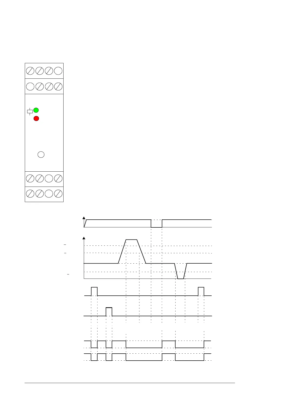
Layout
Operation diagram
A1-A2 Power supply
P1-P2 Measuring circuit with 1…6 sensors
X1-X2 Remote reset push button switch
11-12/14 Output contacts (1)
• 11: Common
• 12: Normally-closed
• 14: Normally-open
21-22/24 Output contacts (2)
• 21: Common
• 22: Normally-closed
• 24: Normally-open
Test/Reset Test and internal reset button
Upper LED (green) Supply voltage present
“R” LED (red) Fault (overtemperature, or broken wire/short circuit in the
sensor circuit)
R
Test /
Reset
P1 P2 X1
22 24 X2
12 14 A2
A1(+) 11 21
< 1.5 kohm
<
20 ohm
Remote reset X1/X2
Test/Reset button
Measurement circuit P1/P2
> 1.8 kohm
Power on / Green LED
Sensor resistance
Overtemperature/
broken wire
detection
Voltage failure/
Reset
Sensor short
circuit
Output contacts
11-14
Tes t Tes t Test/
Reset
11-12
21-24
21-22
On
Off
00 ACS880 ATEX cabinet.book Page 22 Tuesday, May 28, 2019 10:25 AM
 Loading...